7/15 EmpirBus NXT DCM User manual Ver 1.53
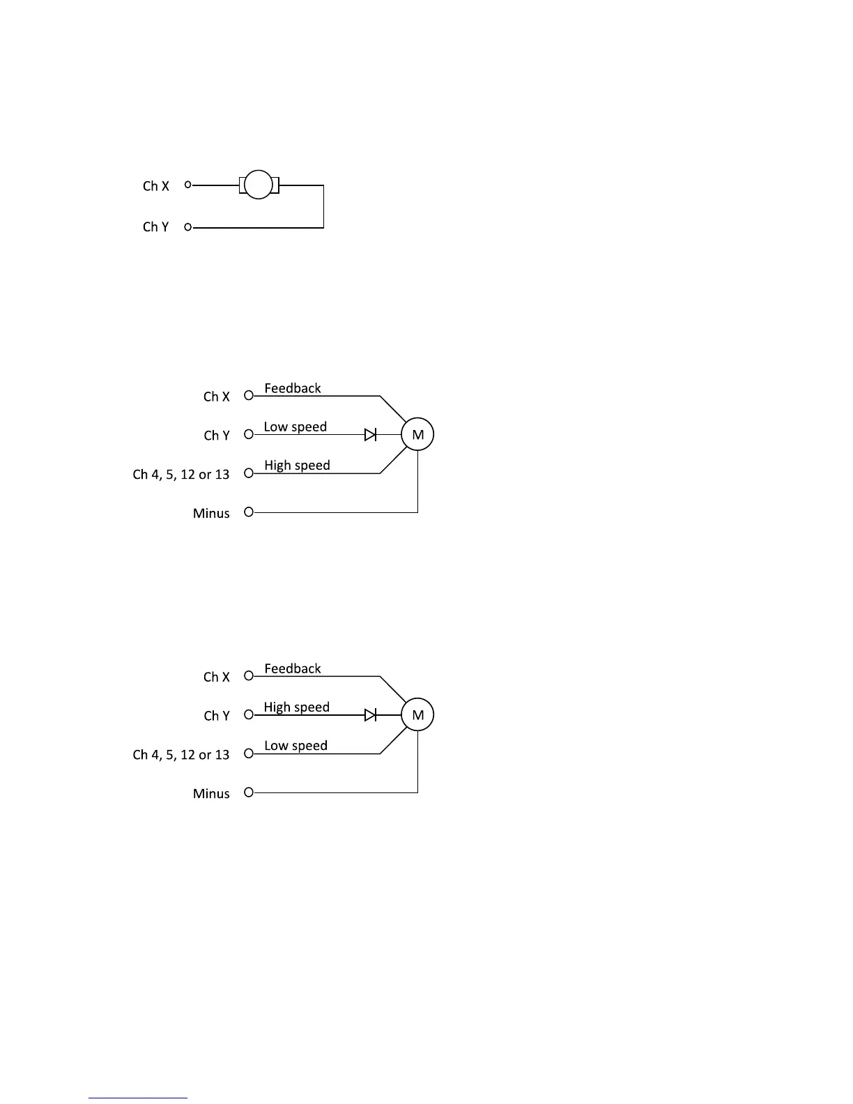
6.2.2!Digital!output!–!half!bridge!
For actuators and other equipment that use shifting polarity, connect the equipment directly
between two channels with minus output capability.
!
6.2.3!Digital!output!–!Window!wiper!
See table 9.1 for models with window wiper capability. Depending of the electrical design of the
window wiper, two different circuits are possible. Most common is window wiper circuit 1. See figure
6.2.
Any channel can be used for Ch X and Ch Y. Channel 4, 5, 12 or 13 is used as high speed channel.
Note: The diode is never connected to channel 4, 5, 12 or 13.
Less common is window wiper circuit 2. See figure 6.3.
Any channel can be used for Ch X and Ch Y. Channel 4, 5, 12 or 13 is used as low speed channel.
Note: The diode is never connected to channel 4, 5, 12 or 13.
!
 Loading...