User’s Manual for Advanced Axial Flux Synchronous Motors and Generators
www.emrax.com Version 4.5 / January 2017 27
5. 3D drawings of EMRAX motors
EMRAX 3D drawings can be downloaded from www.emrax.com
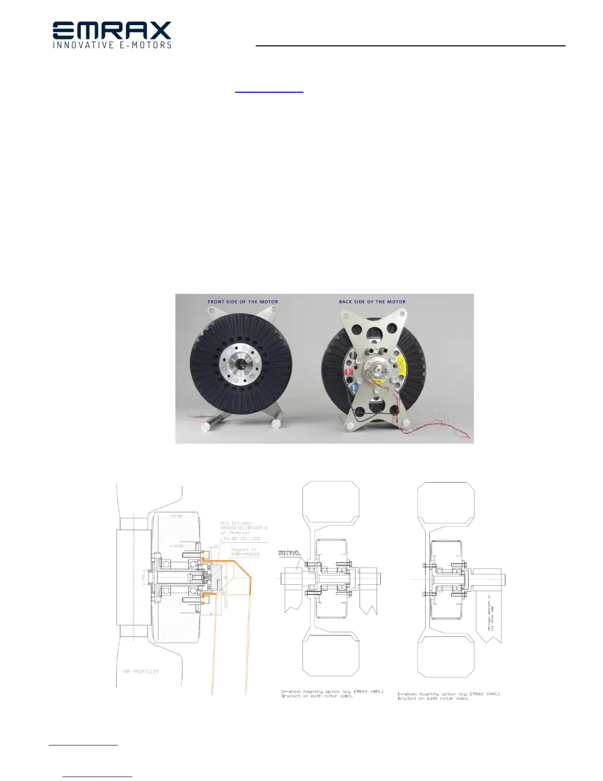
6. Mounting the motor
Only use the drive if properly mounted on threaded bores intended for in the stator. Take a look at EMRAX drawings, where you
can see mounting holes for each EMRAX model. EMRAX has an external rotor, which must not under any condition, not even for
testing, be connected to the frequency converter or the power source, if the motor is not fixed in the manner described above.
Propeller, Flanged Shaft with Inner Splines (FSI) some other drive shaft can be mounted on the front motor side with six M8
threaded bores intended for in the rotor. These screws must be screwed down into the rotor:
at least 14 mm and not more than 15 mm – for EMRAX 188 (M6 instead of M8 threaded boreholes)
at least 15 mm and not more than 16,0 mm - for EMRAX 208
at least 15,5 mm and not more than 16,5 mm - for EMRAX 228
at least 17,5 mm and not more than 18,5 mm - for EMRAX 268
at least 27 mm and not more than 28 mm – for EMRAX 348 (M10 instead of M8 threaded boreholes)
Figure 14: Mounting holes on front and back side of the motor
Figure 15: Mounting options (air propeller / in-wheel)