User’s Manual for Advanced Axial Flux Synchronous Motors and Generators
www.emrax.com Version 4.5 / January 2017 33
The extended motor shaft and the standard motor shaft cannot be replaced once the motor is assembled.
Our shafts are made from hardened steel (42CrMo4).
If custom made shafts are needed, customer can provide a shaft, which must be made precisely according to EMRAX drawings.
The customer can provide a motor shaft or an extended motor shaft. The shaft dimensions must be discussed with the EMRAX
Company before sending the shaft and mounting it in the motor during assembly. The customer can also make a special flanged
shaft for the motor (e.g. with special splines). Another option is to use standard torque adapter (globally available) and mount it
in on the front side of the motor by using special brackets.
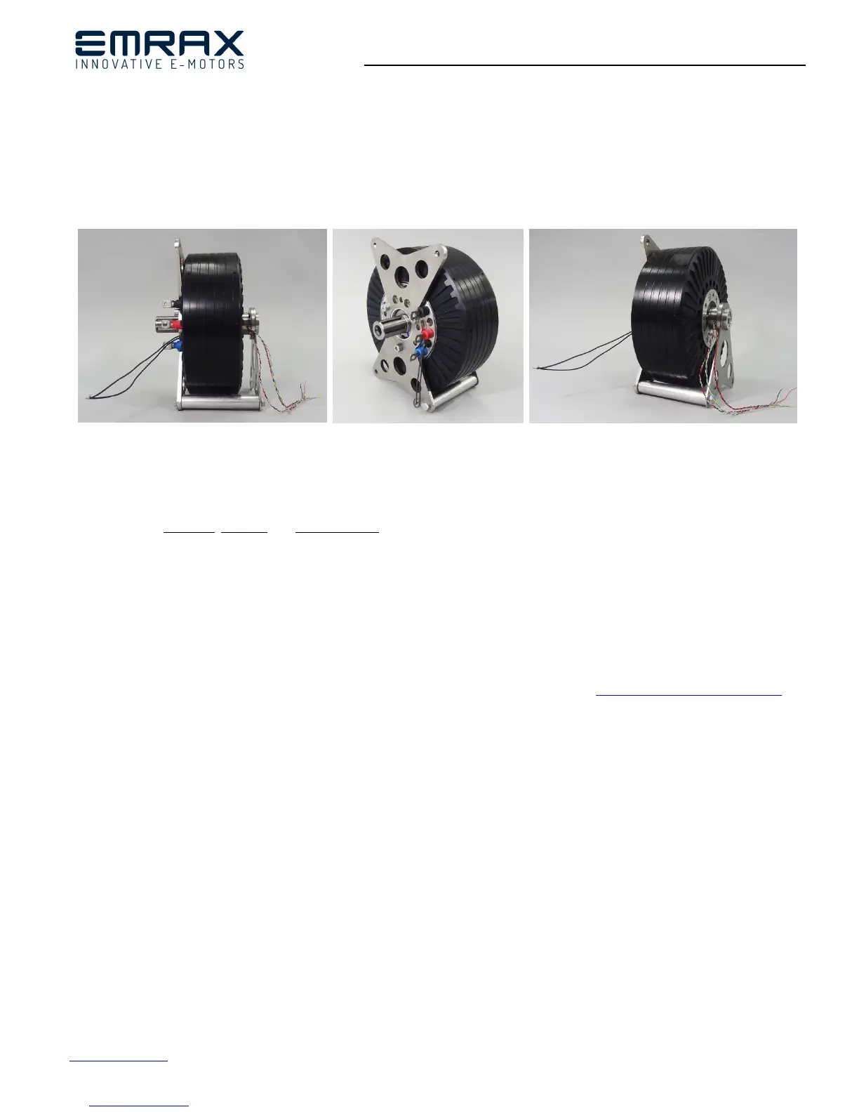
Figure 26: Motor with extended shaft from back motor side
8. Controlling direction, position and rotation speed of EMRAX motors
a) Drive control with sensor:
- For controlling direction, position and rotation speed of the motor a sensor should be used. Sensor types that can be used are:
resolvers, encoders or hall sensors.
- Sensors must be used for e.g. electric vehicles and propellers that have to stop at the exact position (glider planes, where the
propeller has to be put into the fuselage).
- Resolver/encoder has to be precisely mounted onto the motor by a special bracket. Hall sensors have to be mounted in the
motor during assembly of the motor. Sensors with brackets can be ordered from the EMRAX Company, where they are also
mounted. If sensors are not mounted in the EMRAX Company no warranty applies.
!Note:
- It is important that auto tuning (synchronising the electrical and mechanical motor angle) and pre-setting of controller software
is done first. Here is a video, which shows auto-tuning EMRAX motor with Unitek controller: https://youtu.be/yuyPS_RCWQ8
- For every motor one sensor (encoder/resolver/hall) is needed if the motor is used with one controller. When one motor is used
with two controllers (2 sequences of motor phase connectors – 2xUVW) then two sensors should be used (e.g. tandem resolver).
This is when a very high motor current has to be ensured.
- For the EMRAX TWIN application two sensors (tandem resolver mounted on the second motor) and two controllers are
needed. Some controllers (rare controllers) have an option to split the signal from two controllers in only one sensor (usually
encoder), which is mounted on the second motor.
- For more information about sensors, please consult with the controller producers.