Fastlane
®
Pro Swim Unit Installation Fastlane
®
Pro Swim Unit Installation
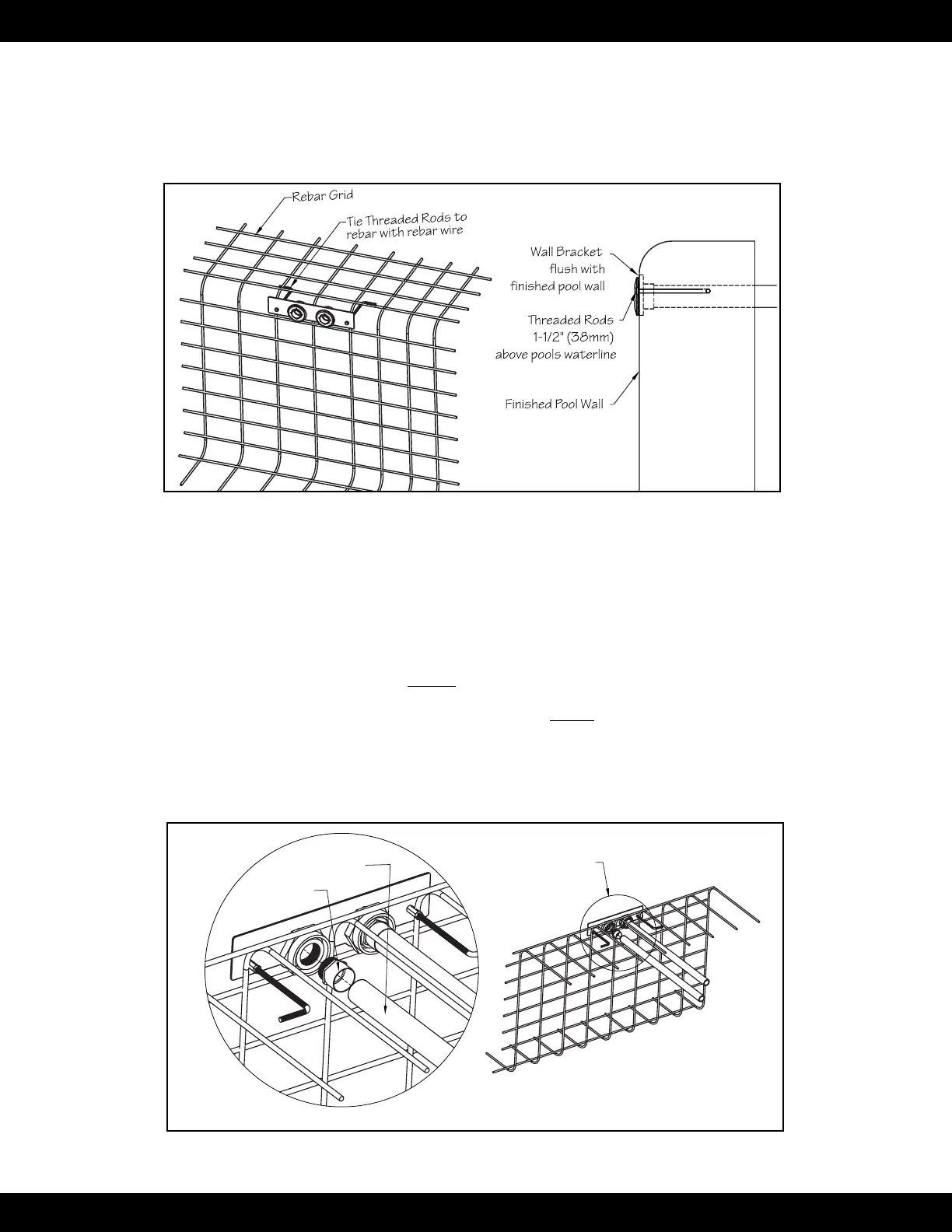
The bracket is to be installed into the pool wall so that the two threaded rods are 1-1/2" (38mm) above the intended
waterline, which is typically halfway up the skimmer. The bottom straight edge of the bracket should be aligned with
the expected waterline. Level and position the bracket so that the PVC surface of the bracket will be ush with the
nished surface of the pool wall. The threaded rods attached to the bracket must be tied back to the rebar of the pool
with rebar wire. Once encased in concrete, these rods will serve as a suitable hanger. The threaded rods must pene-
trate 1-1/4" to 1-1/2" (31,8mm x 38mm) into the nished pool and will be used to hang the Fastlane Pro (Fig 4.18).
Fig. 4.18
The location of the Hydraulic Power Unit should be determined at this point in the installation. Unroll lengths of
1-1/2" (38mm) exible PVC pipe from the back of the wall mount bracket to the Power Unit. Any bends in the exible
pipe MUST be gradual sweeps and not sharp to allow the hydraulic hoses to easily be fed through each conduit.
If the Hydraulic Power Unit is within 25' (7,6m) of the pool: Each length of exible pipe should exit the ground
within 4' (1,2m) of the Power Unit. Approximately 4' (1,2m) of hydraulic hose is required to make the hydraulic con-
nections at the Power Unit.
If the Hydraulic Power Unit is more than 25' (7,6m) away from pool: 25' (7,6m) of exible pipe, a junction box,
and an additional length of exible pipe MUST be employed. It is at the junction box where a step up to a larger diam-
eter hydraulic hose occurs to reduce pressure loss and a potential reduction in performance. In this case, the length of
exible pipe between the wall mount bracket and junction box MUST be 24' 6" (7,5m). This will allow the hydraulic
hoses to terminate just inside the junction box. An additional length of exible pipe coming out of the junction box
should exit the ground within 4' (1,2m) of the Power Unit. See Section 5: Junction Box for detailed information.
Apply Teon thread sealant to the threads of the 1-1/2" (38mm) MPT x FSLIP adapters and thread them into the th-
ru-wall ttings on the backside of the wall mount bracket. Glue the lengths of exible pipe into the adapters (Fig 4.19).
Adapter and Flex Pipe
(See Detail A)
DETAIL A
1-1/2" (38mm)
PVC Flex Pipe
1-1/2" (38mm)
MPT x FSlip
Adapter
Fig. 4.19
20