Cerabar S/Deltabar S/Deltapilot S FOUNDATION Fieldbus Parameter description (FF configuration program)
Endress+Hauser 85
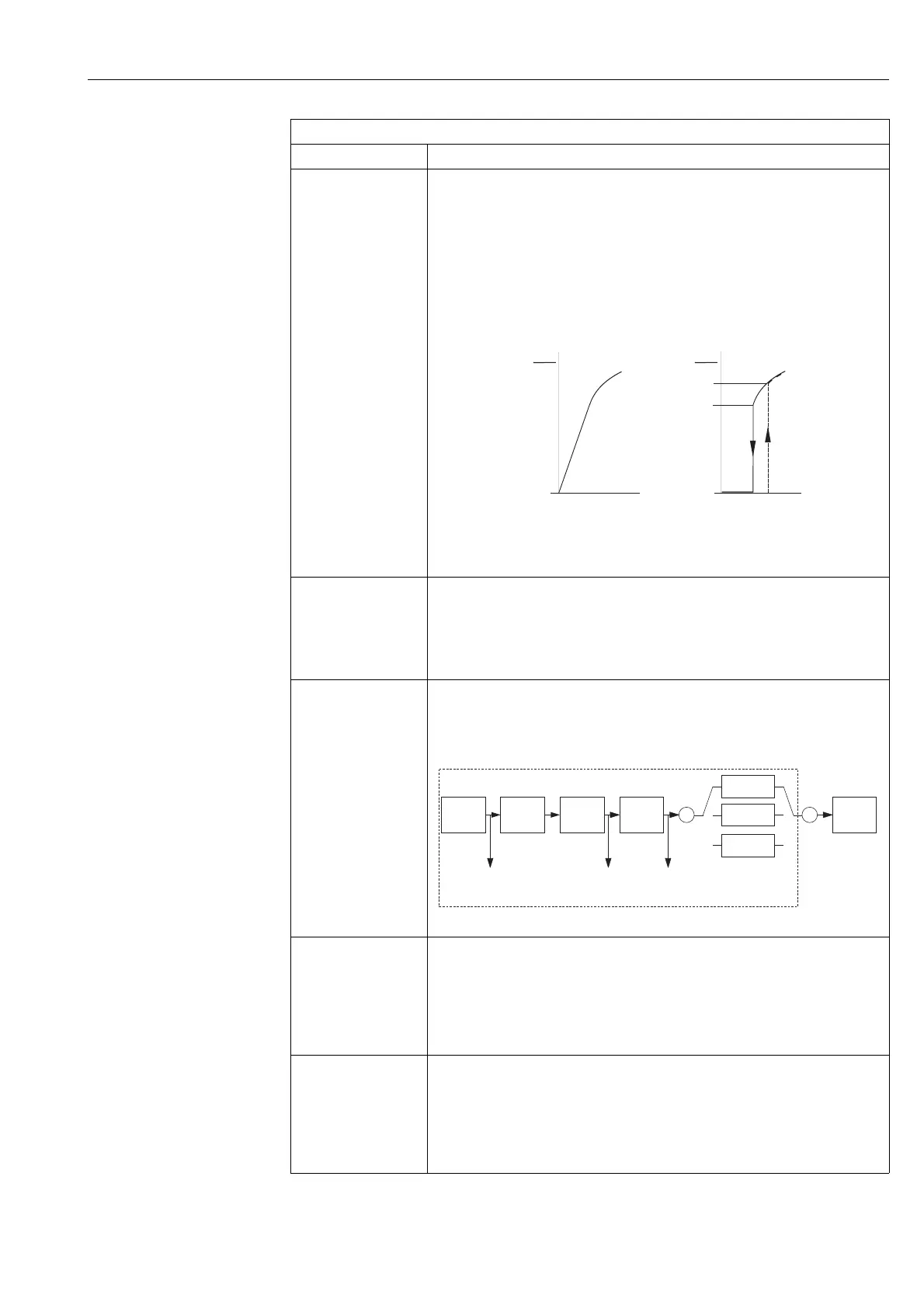
Set. L. Fl. Cut-Off/
SET_LOW_FLOW_CUT_
OFF
Entry
Index: 20
Data type: Float
Access: read, write, OOS
Enter the switch-off point of low flow cut-off.
The hysteresis between the switch-on point and the switch-off point is always 1 % of the end
flow value. → ä 84, Low Flow Cut-Off/LOW_FLOW_CUT_OFF.
Prerequisite:
• Deltabar S differential pressure transmitter
• Low Flow Cut-Off/LOW_FLOW_CUT_OFF = On
Input range:
Switch-off point: 0 to 50% of end flow value (→ ä 58, parameter description for Scale Out/
SCALE_OUT, EU_100 element/MAX. FLOW)
P01-PMD7xxxx-05-xx-xx-xx-000
Factory setting:
5% (of end flow value)
Flow Max/MAX_FLOW
Entry
Index: 21
Data type: Float
Access: read, write, OOS
Enter maximum flow of primary device.
→ See also layout sheet of primary device. The maximum flow is assigned to the maximum
pressure which you enter via Max Press. Flow/MAX_PRESS_FLOW.
Factory setting:
1.0
Pressure/PRESSURE
Display
Index: 22
Data type: Float
Access: read only
Displays the measured pressure after sensor recalibration, position adjustment and damping.
This value corresponds to the Primary Value/PRIMARY_VALUE parameter in the "Pressure"
measuring mode.
P01-xMD7xxxx-05-xx-xx-en-011
Max Press. Flow/
MAX_PRESS_FLOW
Entry
Index: 23
Data type: Float
Access: read, write
Enter maximum pressure of primary device.
→ See layout sheet of primary device. This value is assigned to the maximum flow value
(
→ see Flow Max/MAX_FLOW).
Factory settings:
High sensor limit (
→ see PRESS. SENS HILIM, → ä 198)
Press. Eng. Unit/
PRESSURE_UNIT
Display
Index: 24
Data type: unsigned16
Access: read, write
Display the pressure unit selected.
The pressure unit is selected by means of the Calibration Units/CAL_UNIT parameter
(→ ä 54) in the Pressure Transducer Block.
DP Flow Transducer Block
Parameter Description
6%
5%
➀➁
0%
0%
Q
Q
max
Q
Q
max
Δp Δp
P
PV
Sensor
Analog
Input
Block
Pressure
Level
Flow
Damping
Position
adjust-
ment
Sensor
trim
Transducer Block
PRESSURE_1_
AFTER_DAMPING/
PRESSURE
PRESSURE_1_
AFTER_CALIBRATION/
CORRECTED PRESS.
PRESSURE_1_
AFTER_SENSOR/
SENSOR PRESSURE









 To Next Page