Deltabar S
18 Endress+Hauser
Power supply
Electrical connection Note!
• When using the measuring device in hazardous areas, installation must comply with the corresponding
national standards and regulations and the Safety Instructions or Installation or Control Drawings. o ä 95,
"Safety Instructions" and "Installation/Control Drawings" sections.
• Devices with integrated overvoltage protection must be grounded. o ä 33.
• Protective circuits against reverse polarity, HF influences and overvoltage peaks are installed.
4 to 20 mA HART
P01-xMx7xxxx-04-xx-xx-xx-001
Electrical connection 4 to 20 mA HART
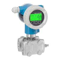
1 Housing
2 Jumper for 4 to 20 mA test signal. See o ä 20, "Measuring a 4 to 20 mA test signal" section.
3 Internal ground terminal
4 External ground terminal
5 4 to 20 mA test signal between positive and test terminal
6 Minimum supply voltage = 10.5 V DC, jumper is set as illustrated in the diagram.
7 Minimum supply voltage = 11.5 V DC, jumper is inserted in "Test" position.
8 Devices with integrated overvoltage protection are labeled OVP (overvoltage protection) here (o ä 33).
PROFIBUS PA
The digital communication signal is transmitted to the bus via a 2-wire connection. The bus also provides the
power supply. For further information on the network structure and grounding, and for further bus system
components such as bus cables, see the relevant documentation, e.g. Operating Instructions BA00034S
"PROFIBUS DP/PA: Guidelines for planning and commissioning" and the PNO Guideline.
Cable specifications:
• Use a twisted, shielded two-wire cable, preferably cable type A
Note!
For further information on the cable specifications, see Operating Instructions BA00034S
"PROFIBUS DP/PA: Guidelines for planning and commissioning", the PNO Guideline 2.092
PROFIBUS PA User and Installation Guideline" and IEC 61158-2 (MBP).
4…20 mA
➅
10.5 V DC
➆
11.5 V DC
4... 20mA
Test
Te st
➀
➁
➂
➃
➄
Test
➇
4... 20mA Test

 Loading...