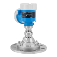
Micropilot FMR67B HART Installation
Endress+Hauser 11
10.2.5 Optimization options
Mapping
Measurement can be optimized by electronically suppressing interference echoes.
See the Confirm distance parameter.
10.3 Mounting the measuring device
10.3.1 Horn antenna 65 mm (2.56 in)
Information about the mounting nozzle
The maximum nozzle length H
max
depends on the nozzle diameter D.
Maximum nozzle length H
max
as a function of the nozzle diameter D
D H
max
80 to 100 mm (3.2 to 4 in) 1 700 mm (67 in)
100 to 150 mm (4 to 6 in) 2 100 mm (83 in)
≥ 150 mm (6 in) 3 200 mm (126 in)
In the case of longer nozzles, reduced measuring performance must be expected.
Please note the following:
• The end of the nozzle must be smooth and free from burrs.
• The edge of the nozzle should be rounded.
• Mapping must be performed.
• Please contact the manufacturer's support department for applications with nozzles
that are higher than indicated in the table.
10.3.2 Horn antenna 65 mm (2.56 in) with alignment unit
UNI flanges with an integrated alignment unit are available for the horn antenna
65 mm (2.56 in). An angle of inclination of up to 15 ° in all directions can be set for the
antenna axis using the alignment unit. The alignment unit is used to optimally align the
measuring signal to the bulk solids.

 Loading...