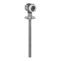
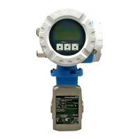
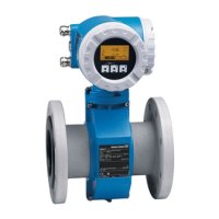
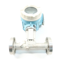
Gammapilot M FMG60 PROFIBUS PA Wiring
Endress+Hauser 19
Terminal Meaning
0 Grounding of the cable shield
1)
1, 2 Power supply
2)
Connection
compartment 2:
3, 4
Connection
compartment 1:
3
1)
, 4
1)
Signal output, depending on communication version:
• 4-20mA with HART
• PROFIBUS PA
• FOUNDATION Fieldbus
Depending on the device version ordered, the signal output is located in connection
compartment 1 or 2 (see below).
For the versions of the Gammapilot M with a fieldbus connector (M12 or 7/8"), the
signal output is wired in connection compartment 2 on delivery and connected to
the fieldbus connector (see the "Fieldbus connectors" section). In this case, the
housing does not need to be opened to connect the signal cable.
5, 6 Pulse input (for cascade mode; is used for master and slave)
7, 8 Pulse output (for cascade mode; is used for slave and end slave)
9, 10, 11, 12 Pt-100 input (4-wire)
13 Connection for display and operating module VU331 (from FHX40); is wired on delivery
and connected to the FHX40 plug.
14 Protective ground
1)
15 Protective ground or grounding of the cable shield
1)
1) Rated cross-section > 1 mm
2
(17 AWG)
2) Rated cross-section max. 2.5 mm
2
(14 AWG)
The cables used at terminals 14 and 15 must at least have the same cross-section as the
cables at terminals 1 and 2.
 Loading...


