Proservo NMS81 Electrical connection
Endress+Hauser 27
6 Electrical connection
6.1 Terminal assignment
D
E
G
F
C
B
A
1
1
1
1
1! ! ! 3
2
2
2! ! ! 4
1
HR
CDI
WP
on
SIM
2
2
3
3
4
4
1
1
2
2
3
3
4
4
5
5
6
6
7
7
8
8
POWER
i
D
E
F
C
B
A
1
1
1
1 3
2
2 4
1
HR
CDI
WP
on
SIM
2
2
3
3
4
4
1
1
2
2
3
3
4
4
5
5
6
6
7
7
8
8
i
G
1
3
2
POWER
A0027012
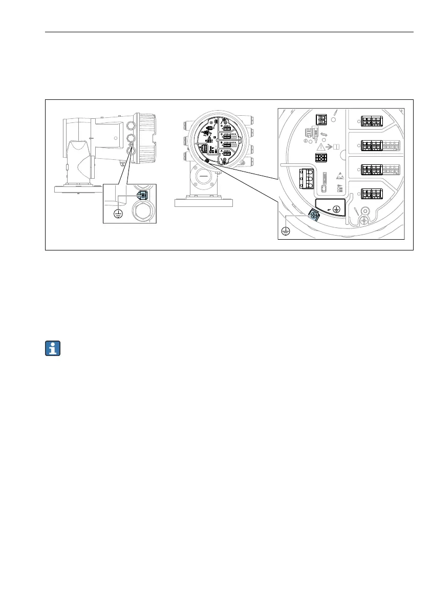
8 Terminal compartment (typical example) and ground terminals
Terminal area A/B/C/D (slots for I/O modules)
Module: Up to four I/O modules, depending on the order code
• Modules with four terminals can be in any of these slots.
• Modules with eight terminals can be in slot B or C.
The exact assignment of the modules to the slots is dependent on the device version
→ 31.
Terminal area E
Module: HART Ex i/IS interface
• E1: H+
• E2: H-
Terminal area F
Remote display
• F1: V
CC
(connect to terminal 81 of the remote display)
• F2: Signal B (connect to terminal 84 of the remote display)
• F3: Signal A (connect to terminal 83 of the remote display)
• F4: Gnd (connect to terminal 82 of the remote display)
Terminal area G (for High voltage AC power supply and Low voltage AC power supply)
• G1: N
• G2: not connected
• G3: L
Terminal area G (for Low voltage DC power supply)
• G1: L-
• G2: not connected
• G3: L+
 Loading...


