Electrical connection Proservo NMS81
40 Endress+Hauser
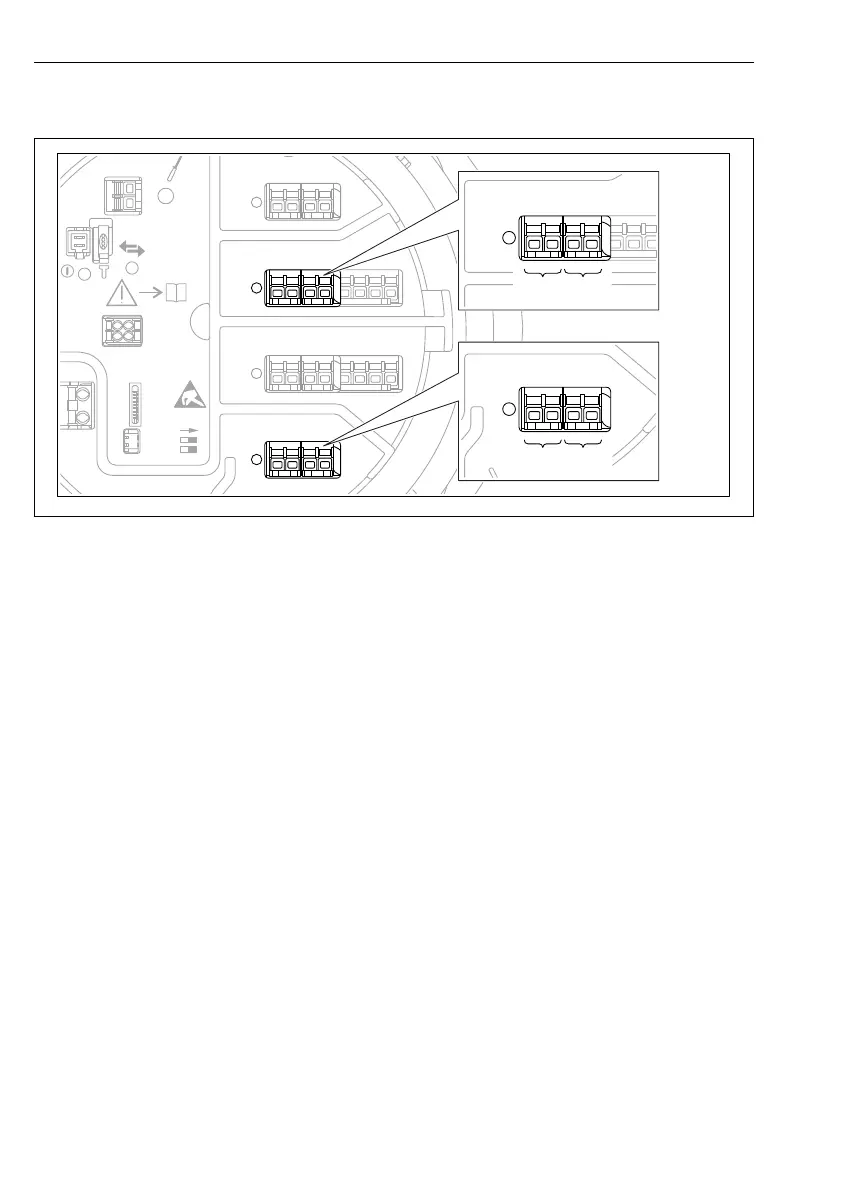
6.1.9 Terminals of the "Digital I/O" module
D
E
F
C
B
A
1
1
1
1 3
2
2 4
1
HR
CDI
WP
on
SIM
2
2
3
3
4
4
1
1
2
2
3
3
4
4
5
5
6
6
7
7
8
8
POWER
i
C
1
2 3 4 5 6 7
C1-2 C3-4
A1-2 A3-4
A
1 2 3 4
A0026424
18 Designation of the digital inputs or outputs (examples)
• Each Digital IO Module provides two digital inputs or outputs.
• In the operating menu each input or output is designated by the respective slot and two
terminals within this slot. A1-2, for example, denotes terminals 1 and 2 of slot A. The same
is valid for slots B, C and D if they contain a Digital IO module.
• For each of these pairs of terminals, one of the following operating modes can be selected in
the operating menu:
• Disable
• Passive Output
• Passive Input
• Active Input