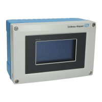
RIA14
2 Endress+Hauser
Function and system design
Measuring principle
a0011145-en
Example of an application of the field indicator
The indicator records an analog measuring signal and shows this on the display. The LC display shows
the current measured value digitally and as a bargraph with limit value violation signalling. The
indicator is looped into the 4 to 20 mA circuit and obtains the required energy from there.
Measuring system Microcontroller controlled indicator in single chamber field housing with illuminated LC display. The
measuring range, decimal point and offset of the indicator can be configured comfortably by means of
three keys in the device with the housing open or by means of a PC with the FieldCare PC software.
Input
Measured variable Current
Measuring range 4 to 20 mA (reverse polarity protection)
Output
Output signal Digital limit switch
Passive, open collector:
I
max
= 200 mA
U
max
= 35 V
U
low/max
= < 2 V at 200 mA
Max. reaction time to limit value = 250 ms
Temperature range: -20 to +80 °C (-4 to +176 °F)
Signal on alarm • No measured value visible on the LC display, no background illumination.
• Open Collector inactive.
Transmission behavior The indicator allows the HART
®
transmission protocol to pass unimpeded.

 Loading...