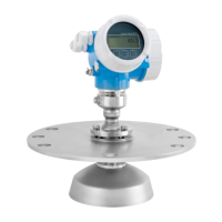
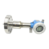
Installation Page: 11 Incoming Acceptance Checks to perform upon receiving the device to ensure completeness and condition.
Transport Instructions for safely transporting the device, including specific guidance for flanged devices and warnings.
Storage Recommendations for proper storage conditions to protect the device from damage and environmental factors.
Installation Conditions Factors to consider for optimal installation, including location, orientation, and pipe conditions.
Dimensions Information on device dimensions and installation lengths, referencing the Technical Information document.
Mounting Location Guidance on selecting suitable mounting locations and avoiding potential issues like air accumulation.
Orientation Recommends optimal sensor orientation (vertical/horizontal) for accurate measurement and lists applicable functions.
Vibrations Advice on securing the device against vibrations and considering separate installation for severe vibration.
Foundations, Supports Guidelines for supporting the sensor, especially for larger nominal diameters, and avoiding casing damage.
Adapters Information on using adapters for installation in larger pipes and calculating pressure loss.
Length of Connecting Cable Instructions for installing remote versions, focusing on cable routing and length limitations based on conductivity.
Installation Step-by-step instructions for installing specific sensor types (Promag W, P, H), including details on seals and ground cables.
Wiring Page: 40 Cable Type Specifies characteristics of cable type A for MODBUS RS485 communication and notes for bus structure.
Shielding and Grounding Explains the importance of shielding and grounding for EMC, explosion protection, and personnel safety.
Connecting the Remote Version Instructions for connecting the sensor and transmitter in a remote configuration, including safety warnings and procedures.
Connecting the Sensor Step-by-step guide for connecting the sensor to the transmitter, including safety precautions and cable termination.
Cable Specifications Detailed specifications for signal and coil current cables, including cross-sections and reinforced cable options.
Terminal Assignment Lists permissible submodule combinations and their corresponding terminal assignments on the transmitter's I/O board.
Transmitter Connection Procedures and safety warnings for connecting the transmitter, including cable routing and fieldbus cable considerations.
Potential Equalization Explains the importance of potential equalization for accurate measurement and provides connection examples for different conditions.
Degree of Protection Details how to maintain the IP 67 (NEMA 4X) protection rating after installation and servicing.
Post-Connection Check A checklist to perform after electrical installation to ensure correct connections and grounding.
Operation Page: 53 Quick Operation Guide Outlines the different options for configuring and commissioning the device, including local display and software programs.
Local Display Describes the functions and elements of the local display for reading parameters and configuring the device.
Icons Provides a reference for icons used on the display to indicate measured variables, status, and errors.
General Notes General guidelines for using the function matrix, including function selection, data entry, and mode disabling.
Error Messages Covers types of errors (system/process) and how they are displayed, including fault and notice messages.
Type of Error Differentiates between system errors and process errors and their display priority.
Error Message Type Explains the classification of errors as "Fault" or "Notice" messages and their impact on outputs.
MODBUS RS485 Technology Describes the MODBUS RS485 fieldbus system, distinguishing between master and slave devices.
MODBUS Telegram Explains the structure of MODBUS telegrams (request and response) and their fields.
MODBUS Function Codes Lists and describes the MODBUS function codes supported by the device for read, write, and test operations.
MODBUS Register Addresses Explains how register addresses are used to access device parameters and the different address models.
MODBUS Auto-Scan Buffer Describes the auto-scan buffer for grouping device parameters and configuring the scan list.
Operating Options Presents options for operating and configuring the device, including FieldCare and device drivers.
FieldCare Introduces FieldCare as an Asset Management Tool for configuring and diagnosing intelligent field devices.
Hardware Settings Covers hardware settings like write protection, device address, terminating resistors, and output configurations.
Commissioning Page: 79 Function Check Reminds users to complete post-installation and post-connection checks before startup.
Quick Setup Introduces Quick Setup menus for configuring device parameters and additional functions easily.
Quick Setup Batching Guides through the "Batching" Quick Setup for configuring batching operations and controlling filling processes.
Quick Setup Communication Covers the "Communication" Quick Setup for establishing serial data transfer and configuring communication parameters.
Adjustment Covers device adjustment procedures, specifically for empty-pipe/full-pipe conditions.
Data Memory Describes the HistoROM data storage modules (S-DAT, T-DAT) and the F-CHIP for extending functionality.
F-CHIP (Function-Chip) Describes the F-CHIP as a microprocessor chip that extends device functionality with software packages.
Troubleshooting Page: 96 Check the Display Steps to troubleshoot issues related to the device display and output signals.
System Error Messages Lists common system errors, their causes, and recommended remedies, including hardware and software issues.
Process Error Messages Details process-specific errors, their causes, and remedies, focusing on batching and adjustment-related issues.
Response of Outputs to Errors Explains how outputs (current, pulse, frequency) and totalizers respond to errors and the effect of positive zero return.
Spare Parts Lists available spare parts for transmitter components and their ordering information.
Return Procedures and precautions for returning the device for repair or calibration, including contamination declaration.
Disposal Reminder to observe local regulations for device disposal.
Software History Provides a history of software versions and their corresponding manual versions.
Technical Data Page: 116 Application Specifies the intended application and main use case for the measuring device.
Input Variables Details the measured variable, measuring range, operable flow range, and input signal characteristics.
Output Variables Lists specifications for current, pulse, and frequency outputs, including active/passive modes and configurations.
MODBUS RS485 Technical specifications related to the MODBUS RS485 communication interface.
Power Supply Covers electrical connections, supply voltage ranges, cable entries, power consumption, and behavior during power failure.
Human Interface Describes the display elements, operating elements, and language groups available for user interaction.
Ordering Information Directs users to contact Endress+Hauser service for detailed ordering information and order codes.
Accessories Mentions the availability of various accessories for transmitter and sensor, orderable separately.
Documentation Lists available documentation, including technical information and device function descriptions.
