Proline Promag 53 MODBUS RS485 Wiring
Endress+Hauser 47
4.3 Connecting the measuring unit
4.3.1 Terminal assignment
"
Caution!
Only certain combinations of submodules (see Table) on the I/O board are permissible. The
individual slots are marked and assigned to the following terminals in the connection compartment
of the transmitter:
• "INPUT / OUTPUT 3" slot = terminals 22/23
• "INPUT / OUTPUT 4" slot = terminals 20/21
!
Note!
The electrical values of the inputs and outputs can be found in the "Technical data" section.
4.3.2 Transmitter connection
#
Warning!
• Risk of electric shock. Switch off the power supply before opening the device. Do not install or
wire the device while it is connected to the power supply. Failure to comply with this precaution
can result in irreparable damage to the electronics.
• Risk of electric shock. Connect the protective earth to the ground terminal on the housing before
the power supply is applied (not required for galvanically isolated power supply).
• Compare the specifications on the nameplate with the local supply voltage and frequency. The
national regulations governing the installation of electrical equipment also apply.
1. Unscrew the connection compartment cover (a) from the transmitter housing.
2. Feed the power supply cable (b), the signal cable (d) and the fieldbus cable (e) through the
appropriate cable entries.
3. Perform wiring in accordance with the respective terminal assignment and the associated
wiring diagram.
"
Caution!
– Risk of damage to the fieldbus cable!
Observe the information about shielding and grounding the fieldbus cable. → ä 41
– We recommend that the fieldbus cable not be looped using conventional cable glands. If you
later replace even just one measuring device, the bus communication will have to be
interrupted.
4. Screw the cover of the connection compartment (a) back onto the transmitter housing.
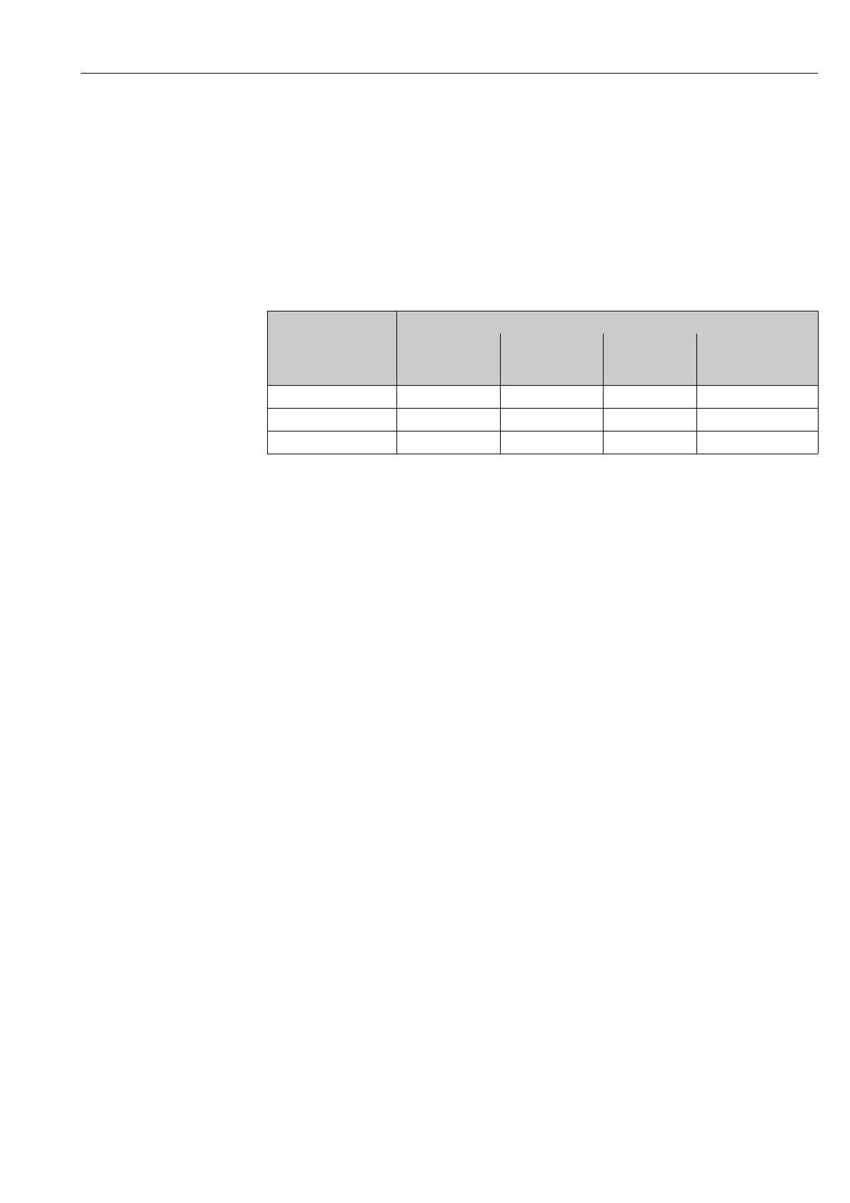
Terminal No. (inputs / outputs)
Order version 20 (+) / 21 (-)
Submodule on
slot No. 4
22 (+) / 23 (-)
Submodule on
slot No. 3
24 (+) / 25 (-)
Fixed on
I/O board
26 = B (RxD/TxD-P)
27 = A (RxD/TxD-N)
Fixed on I/O board
53***-***********Q - - Status input MODBUS RS485
53***-***********7 Relay output 2 Relay output 1 Status input MODBUS RS485
53***-***********N Current output Frequency output Status input MODBUS RS485