Proline Promag 53 MODBUS RS485 Installation
Endress+Hauser 17
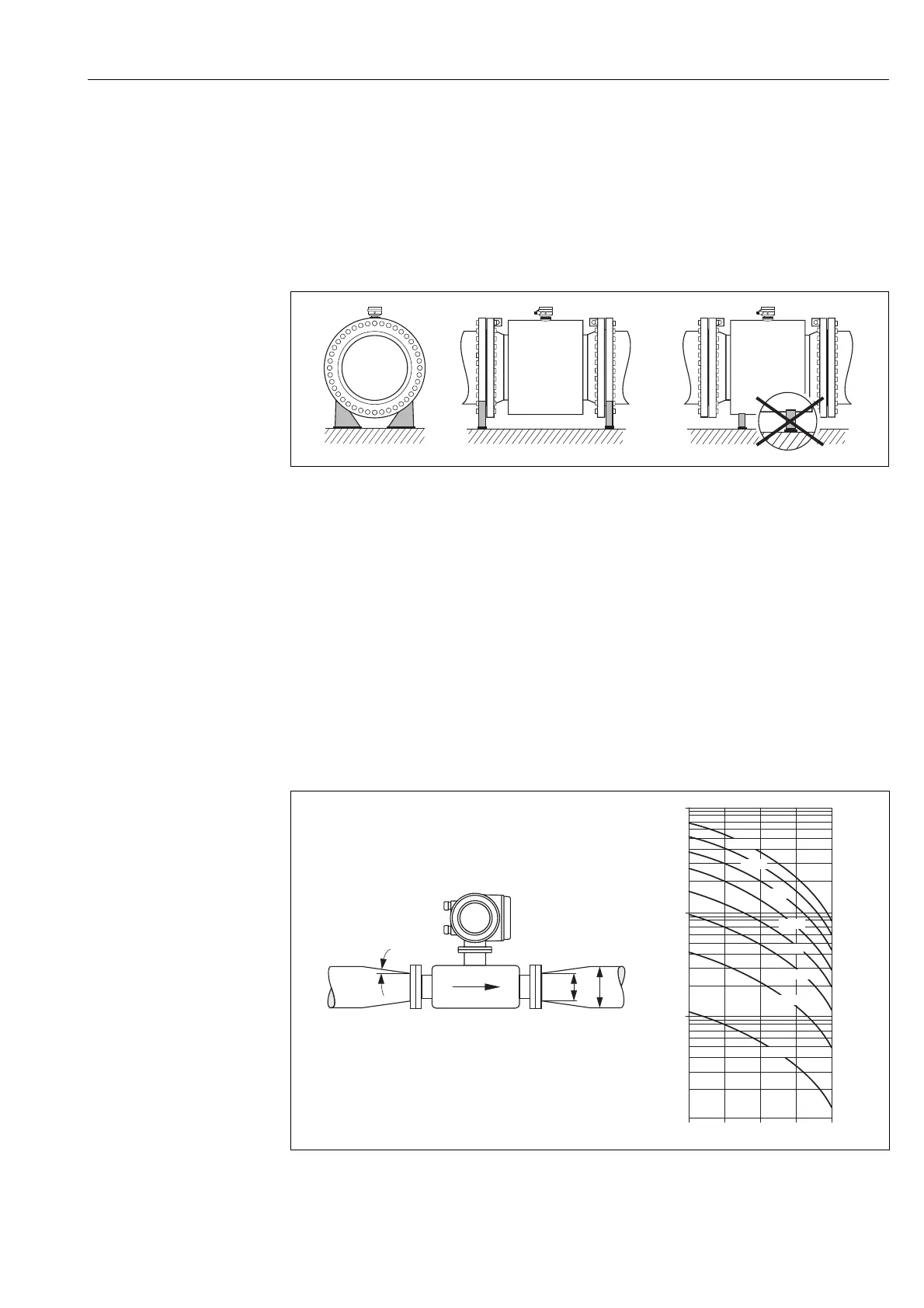
3.2.6 Foundations, supports
If the nominal diameter is DN ≥ 350 (14"), mount the sensor on a foundation of adequate load-
bearing strength.
"
Caution!
Risk of damage.
Do not support the weight of the sensor on the metal casing: the casing would buckle and damage
the internal magnetic coils.
a0003209
Fig. 14: Correct support for large nominal diameters (DN ≥ 350/14")
3.2.7 Adapters
Suitable adapters to DIN EN 545 (double-flange reducers) can be used to install the sensor in larger-
diameter pipes. The resultant increase in the rate of flow improves measuring accuracy with very
slow-moving fluids.
The nomogram shown here can be used to calculate the pressure loss caused by cross-section
reduction.
!
Note!
The nomogram only applies to liquids of viscosity similar to water.
1. Calculate the ratio of the diameters d/D.
2. From the nomogram, read off the pressure loss as a function of fluid velocity (downstream from
the reduction) and the d/D ratio.
A0011907
Fig. 15: Pressure loss due to adapters
100
10
0.5
d/D
[mbar]
0.6 0.7 0.8 0.9
1 m/s
2 m/s
3 m/s
4 m/s
5 m/s
6 m/s
7 m/s
8 m/s
1
D
d
max. 8°