Operation Proline Promag 53 MODBUS RS485
76 Endress+Hauser
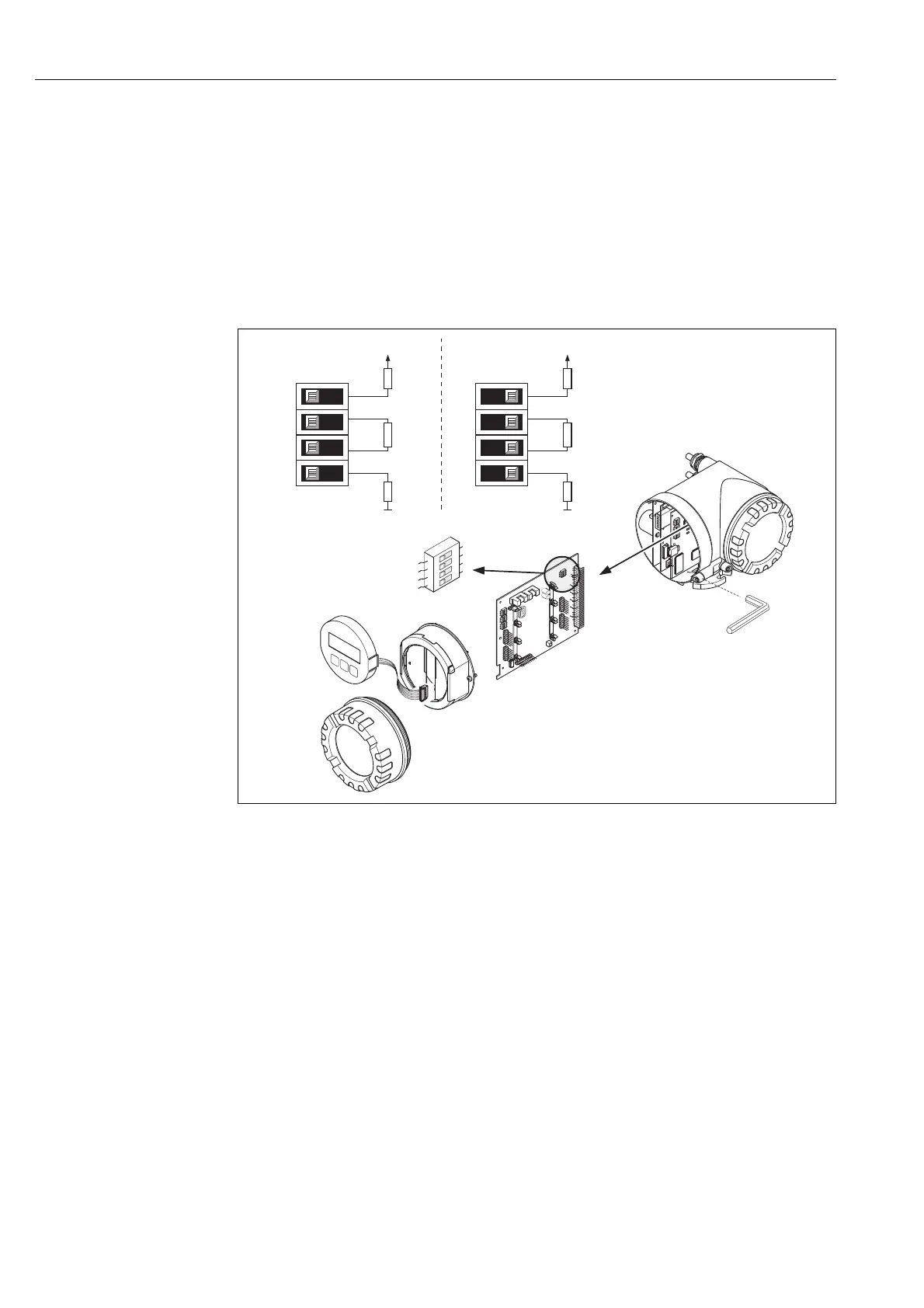
5.7.3 Configuring the terminating resistors
It is important to terminate the MODBUS RS485 line correctly at the start and end of the bus
segment since impedance mismatch results in reflections on the line which can cause faulty
communication transmission.
#
Warning!
Risk of electric shock. Exposed components carry dangerous voltages.
Make sure that the power supply is switched off before you remove the cover of the electronics
compartment.
The miniature switch for termination is located on the I/O board (see Figure):
a0004392
Fig. 51: Configuring the terminating resistors
A = Factory setting
B = Setting at the last transmitter
!
Note!
It is generally recommended to use external termination since if a device that is terminated
internally is defect, this can result in the failure of the entire segment.
1
2
3
4
W
E
N
O
1
2
3
4
W
E
N
O
1
2
3
4
W
E
N
O
INPUT/OUTPUT
4
INPUT/OUTPUT
3
1
2
3
4
W
E
N
O
1
2
3
4
W
E
N
O
1
2
3
4
W
E
N
O
1
2
3
4
W
E
N
O
1
2
3
4
W
E
N
O
390 W
+5V
A
3
4
1
2
OFF ON
220W
390 W
SW1
390 W
+5V
B
3
4
1
2
OFF ON
220W
390 W
SW1