Proline Promag 53 MODBUS RS485 Installation
Endress+Hauser 27
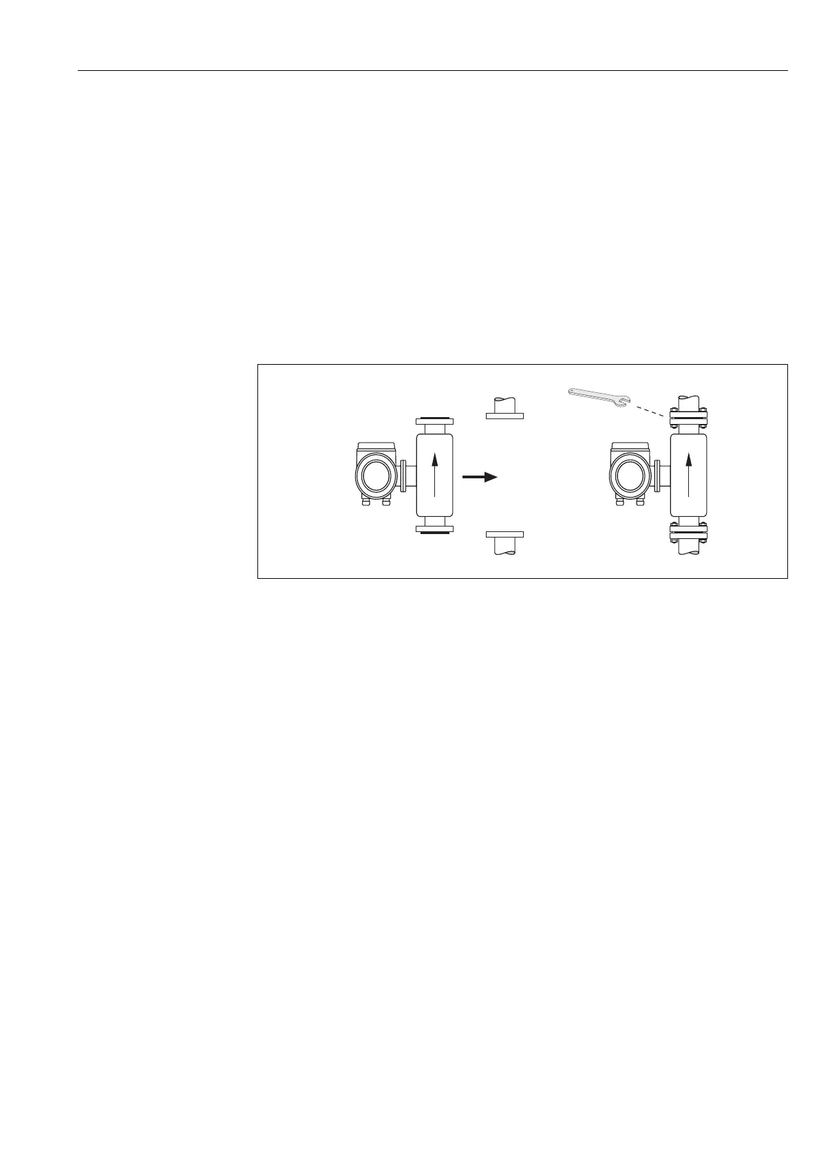
3.3.2 Installing the Promag P sensor
"
Caution!
• The protective covers mounted on the two sensor flanges guard the PTFE lining, which is turned
over the flanges. Consequently, do not remove these protection plates until immediately before
the sensor is installed in the pipe.
• Protection plates must remain in place while the device is in storage.
• Make sure that the lining is not damaged or removed from the flanges.
!
Note!
Bolts, nuts, seals, etc. are not included in the scope of supply and must be supplied by the customer.
The sensor is designed for installation between the two piping flanges:
• It is essential that you observe the necessary screw tightening torques on → ä 28.
• If grounding disks are used, follow the mounting instructions which will be enclosed with the
shipment.
A0011908
Fig. 18: Installing the Promag P sensor
Seals
Comply with the following instructions when installing seals:
• PFA or PTFE lining → seals are not required.
• Only use seals that comply with DIN EN 1514-1 for DIN flanges.
• Make sure that the seals do not protrude into the piping cross-section.
"
Caution!
Risk of short circuit! Do not use electrically conductive sealing compound such as graphite. An
electrically conductive layer could form on the inside of the measuring tube and short-circuit the
measuring signal.
Ground cable
• If necessary, special ground cables can be ordered as accessories for potential equalization,
→ ä 94.
• For information on potential equalization and detailed installation instructions for using ground
cables, please refer to → ä 49.