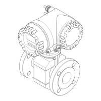
Proline Promag 53 MODBUS RS485 Troubleshooting
Endress+Hauser 107
9.6 Spare parts
The previous sections contain a detailed troubleshooting guide. → ä 96
The measuring device, moreover, provides additional support in the form of continuous self-
diagnosis and error messages.
Fault rectification can entail replacing defective components with tested spare parts. The illustration
below shows the available scope of spare parts.
!
Note!
You can order spare parts directly from your Endress+Hauser service organization by providing the
serial number printed on the transmitter's nameplate. → ä 7
Spare parts are shipped as sets comprising the following parts:
• Spare part
• Additional parts, small items (screws, etc.)
• Mounting instructions
•Packaging
a0004783
Fig. 60: Spare parts for transmitter (field and wall-mount housings)
1 Power unit board (85 to 260 V AC, 20 to 55 V AC, 16 to 62 V DC)
2 Amplifier board
3 I/O board (COM module), flexible assignment
4 Pluggable sub-modules (inputs/outputs); ordering structure → ä 94
5 S-DAT (sensor data memory)
6 T-DAT (transmitter data memory)
7 F-CHIP (function chip for optional software)
8 Display module
INPUT/OUTPU
T
4
INPUT/OU
TPUT
3
1
2
3
4
W
E
N
O
1
2
3
4
W
E
N
O
1
2
3
4
W
E
N
O
1
2
3
4
W
E
N
O
1
2
3
4
8
5
6
7

 Loading...


