Do you have a question about the Endress+Hauser ria45 and is the answer not in the manual?
Explains the purpose and scope of the operating instructions for the device lifecycle.
Details safety symbols, electrical symbols, and symbols for information and graphics used in the manual.
Explains symbols used to denote permitted actions, tips, references, and steps.
Specifies qualifications and authorization needed for personnel performing installation, commissioning, and maintenance.
Defines the device's purpose, capabilities, and limitations, including not being for hazardous areas.
Guidelines for operating the device safely, including protective equipment and preventing modifications.
States the device is designed and tested to meet safety requirements and complies with EC directives.
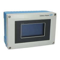
Explains how to identify the device using its nameplate and its components.
Lists all items included in the device package: panel meter, instructions, fasteners, and distance piece.
Confirms the device meets EU directives and safety standards, marked by CE.
Procedures for checking, transporting, and storing the device, including permitted conditions.
Details panel mounting, orientation, and environmental conditions affecting device operation and display.
Step-by-step instructions for physically installing the device into a panel.
A checklist to ensure the device is correctly installed and secured before operation.
Instructions for electrical connections, including loop power supply, sensors, and safety warnings.
Verifies correct wiring, connections, and terminal security after installation.
Describes the device's physical keys and their functions for local operation and menu navigation.
Details how to use the three keys to navigate menus, select parameters, and change values.
Explains how to configure the device using PC software for advanced setup and data management.
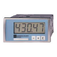
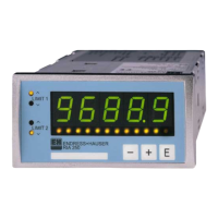
Explains the LC display layout, segment displays, dot matrix, and status LEDs.
Lists and explains various icons used on the device display for status and information.
A summary of device menus and functions for quick reference during operation.
Final checks before commissioning and initial power-on procedure.
Overview of local and PC-based configuration options for the device.
Instructions on how to lock or unlock device configuration using a user code.
Step-by-step guide to setting up device parameters based on application requirements.
How to choose the application type (e.g., Differential pressure) and input channel configuration.
Setting up input parameters for current, voltage, RTD, or thermocouple signals.
Defining calculations like sum, difference, or linearization for input channels.
Assigning inputs or calculated values to analog outputs and setting their signal type.
Setting up relays with limit values, functions, and hysteresis for monitoring.
Setting up access codes for security and saving current configurations.
Customizing display elements like contrast, brightness, and alternating time between channels.
Configuring the device for overfill protection according to TRbF 510 regulations.
Accessing advanced settings for optimal device adaptation to application conditions.
Describes how the device operates after commissioning, including display modes and memory.
Explains device self-checks, error reactions, and detection of circuit issues.
Options for resetting device parameters to factory defaults or user-defined setups.
Lists accessories like extension relays and input cards for extending device functionality.
Lists accessories for PC communication, such as interface cables and Commubox.
General advice and warnings for troubleshooting device issues.
Details error codes displayed by the device and their corresponding meanings.
Lists specific error codes (Fxxx, Cxxx) related to device malfunctions and their remedies.
Information on how to order replacement parts, including a diagram and item list.
Specifies input types, measured variables, and measuring ranges for the device's universal inputs.
Details the specific input ranges supported for current, voltage, resistance, RTD, and thermocouples.
Information on the device's capability for input signal linearization using up to 32 points.
Details the analog output signals, current/voltage capabilities, and loop power supply specifications.
Lists the supported current (0/4-20mA) and voltage (0-10V, etc.) output ranges.
Details electrical connections, supply voltage, and power consumption.
Diagram showing terminal assignments for inputs, outputs, and power supply.
Details accuracy specifications for various input types and measurement ranges.
Lists the maximum measured errors (OMR) for different input types and ranges.
Provides instructions for mounting location and orientation of the device.
Specifies ambient and storage temperature ranges, operating height, and climate class.
Provides design dimensions, weight, housing material, and terminal specifications.
Describes display elements, operating elements, and remote operation methods.
Explains the 5-digit LC display, dot matrix, signaling LEDs, and display range.
Lists CE mark, Ex approval information, and other relevant standards.
Lists references for system components, technical information, Ex safety instructions, and SIL safety manual.
Details calculation steps for level measurement using differential pressure sensors.
Explains how to calculate filling level from pressure difference, density, and gravitational acceleration.
How to calculate volume from height using linearization, possibly with FieldCare support.
Details parameters for resetting min/max values and configuring display options for channels.
Lists parameters for application configuration, signal type, range, and connection type.
Configures the lower and upper limits of the measuring range for analog inputs.
Selects the input type: Current, Voltage, RTD, or TC.
Configures the input signal range based on the selected signal type.
Defines unit of measurement, temperature units, and offset for signals.
Selects calculation method, assigns Tag, and defines unit for math channels.
Sets assignment, signal type, and range for analog outputs.
Configures relay source, function, and setpoints.
Sets access codes, overfill protection, and device reset parameters.
Accesses device status, logs, and information like serial number and order code.
Accesses advanced device settings beyond the standard setup menu.
Expert settings for bar graph, decimal places, and signal damping.
Expert settings for analog output and relay failure modes.
Expert settings for simulating analog outputs and relays.
| Power supply | 24 V DC |
|---|---|
| Display | LCD |
| Protection | IP66/IP67 |
| Communication | HART |
| Material | Stainless Steel, Aluminum |