Operation RIA45
16 Endress+Hauser
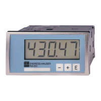
6.2 Display and device status indicator/LED
The device provides an illuminated LC display which is split into two sections. The segment
section displays the value of the channel and additional information and alarms.
In the dot matrix section, additional channel information, such as the TAG, unit or bar
graph, is displayed in the display mode. Operating text in English is displayed here during
operation.
The parameters for configuring the display are explained in detail in Section "Configuring
the device".
A0010223
4 Display of the device
1 Channel display: 1: analog input 1; 2: analog input 2; 1M: calculated value 1; 2M: calculated value 2
2 Dot matrix display for TAG, bar graph and unit
3 Limit value indicators in the bar graph
4 "Operation locked" indicator
5 Green LED; on - supply voltage applied
6 Red LED; on - error/alarm
7 Yellow LED; on - relay 1 energized
8 Yellow LED; on - relay 2 energized
9 Minimum/maximum value indicator
In the event of an error, the device switches automatically between displaying the error
and displaying the channel, → 35 and → 40.
6.3 Icons
6.3.1 Display icons
Device is locked/operating lock; the device setup is locked against changes to parameters, the
display can be modified.
1 Channel one (Analog in 1)
2 Channel two (Analog in 2)
1M First calculated value (Calc value 1)
2M Second calculated value (Calc value 2)
Max Maximum value/value of the maximum indicator of the channel displayed
Min Minimum value/value of the minimum indicator of the channel displayed
In the event of an error:
The display shows: , the measured value is not displayed