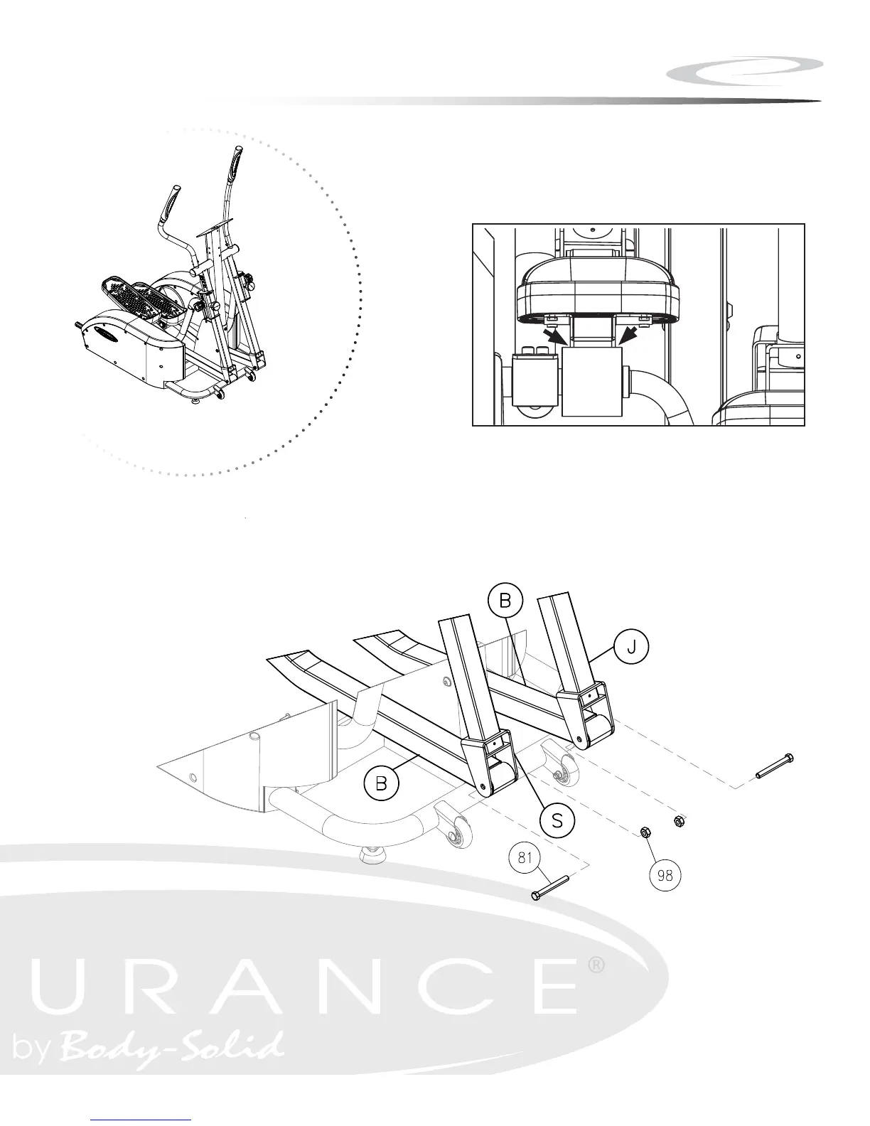
Above shows STEP 5 assembled and completed.
7
Assembly
Figure 5
Locate bag labeled Figure 5. Locate Right
Pedal Tube Assembly. Secure Pedal Tube
assembly to the Handrail Assembly with one
M10*81.5 Hex Bolt and one M10*1.5 Hex
Nut. Please ensure that Pedal Arm is aligned
in the center of roller wheel while tightening
M10*81.5 bolt (Figure 5a). Repeat for the
left side.
Note: It is recommended that 2 adults
align and secure the Pedal Tube Assemblies
to the Handrail Assemblies.
Figure 4
Locate bag labeled Figure 4. Lift and
place left Linkage onto Shaft Sleeve and
align holes. Secure Linkage to unit using
four M8*12 mm Hex Bolts. Repeat for right
side.
Note: The Linkage is secured to the sleeve
with three M8*12 Hex Bolts on the top of
the Linkage and one M8*12 Hex Bolt on the
bottom of the Linkage.
Figure 4
Figure 5
M8*12 HEX BOLT
M10*81.5 HEX BOLT
M10*1.5 HEX NUT
SLEEVE
LINKAGE
HANDRAIL ASSEMBLY
PEDAL TUBE ASSEMBLY
Figure 5a