10
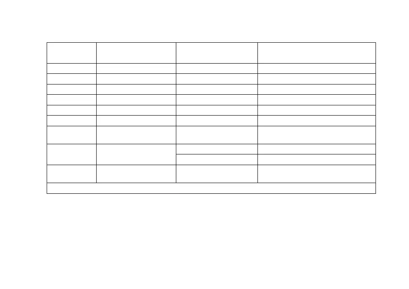
Table 2.1
Designation Interface Designation
Additional software and hardware
options
O* Optical interface (OI) S Alarm relay
B M-BUS Q Load control relay
E RS232 Y 2 metering directions
A RS485 D External display
P PLC U Power quality parameters
G GSM V* Electronic seals
N Ethernet J
Optional connection of a backup
power source
R1
Radio interface with
a built-in antenna
L LCD backlighting
F Magnetic field sensor
R2
Radio interface with
an external antenna
Z Extended set of parameters
* – by default, included in all meter versions
2.2.2 Meter versions, accuracy classes, the meter constant and the position of the comma when displaying
energy values on the LCD, depending on the nominal voltage (U
NOM
), nominal (I
NOM
) or base (I
b
) and maximum
(I
MAX
) current, are shown in Table 2.3.
 Loading...