22 23
pins 17 – in meter versions with RS485 interface (versions with A), pins of RS485 interface, left A, middle B,
right GND (duplicate the pins of the socket 19);
in meter versions with an Ethernet interface (version with N), built-in Ethernet module reset contacts, middle
RST, right GND.
In meter designs with RF01 module, RS485 technological interface for configuring the integrated radio module,
left A, middle B, right GND;
pins 19 — depending on the meter version: socket of the built-in Ethernet module; HF – connector for connecting
an external antenna; plug.
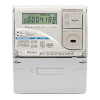
Figure a) first variant of CE308 S31, S34 meter pins designation