10
5.4 Hydraulic Oil
The hydraulic oil shown in the following table is approved for use
with the pump.
Temperature Range Approved Hydraulic Oil
°C °F
15 to 60 60 to 150 ADV Hydo 10 (SAE 10W)
Failure to use the specified oil may result in damage to
pump and other hydraulic components and will void the product
warranty.
Be sure that the oil is clean and that it is poured from a clean
container. The oil cleanliness should be maintained to a minimum
cleanliness level of 18/16/13 per the ISO4406 standard. If the oil
has a milky, cloudy or dark appearance, it should be changed
immediately as described in the pump maintenance instructions.
Use only a high quality hydraulic oil that meets the specifications
shown in the approved hydraulic oil table. Add oil only when all
system components are fully retracted, or the system will contain
more oil than the reservoir can hold.
For detailed instructions explaining how to add oil to the pump
reservoir, refer to the Smart Tensioning Pump instruction sheet
(document L4186).
5.5 Hydraulic Couplers
Each tensioner includes a male quick-disconnect style hydraulic
coupler. The Smart Tensioning Pump, and the connecting hoses
include similar male and female couplers.
Failure to observe the following precautions may result in
death or serious personal injury.
• On the Smart Tensioning Pump, pressure is automatically
relieved and directed to the pump reservoir when the motor
is stopped. However, as a precaution after stopping the motor
and before disconnecting electrical power, always verify that
zero (0) psi/bar is indicated on both the pump pressure gauge
and on the pump touchscreen HMI pressure readout.
• Be sure that pump motor is OFF before connecting or
disconnecting any couplers.
• Do not pressurize disconnected couplers. All couplers must
be correctly and completely fastened together before applying
pressure.
• Never disconnect any couplers without first unloading the
tensioners and releasing hydraulic pressure.
• Never attempt to relieve pressure by loosening a fitting or by
unseating a coupler check ball or seat.
All system pressure must be released prior to making
connections. If there is any pressure trapped in the hydraulic
components, it will be not possible to connect or disconnect
hoses using the couplers.
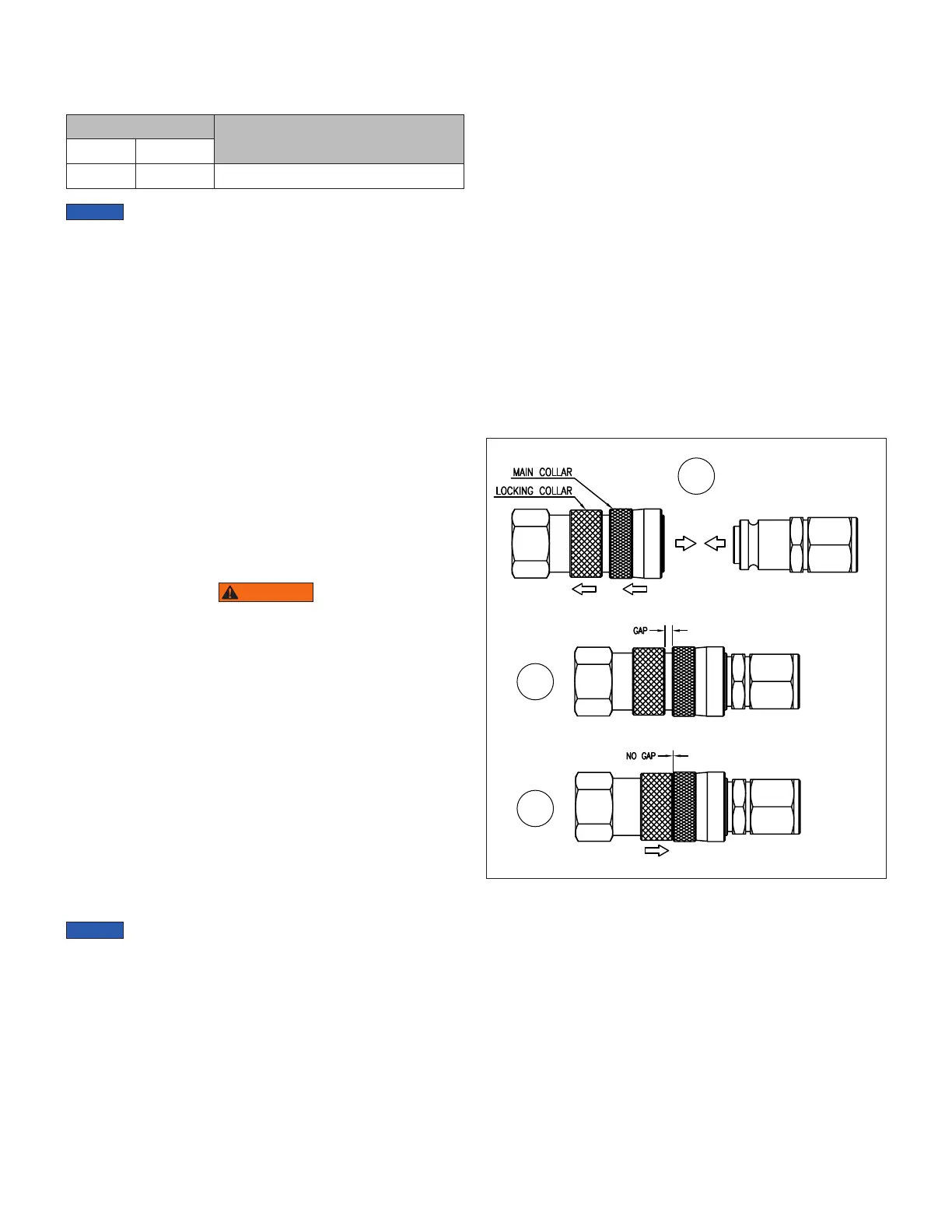
To Connect Couplers:
See Figure 8.
1. Before making any connections, be sure that the pump
pressure gauge and the touchscreen HMI pressure readout
both indicate (0) psi/bar.
2. Be sure that couplers are free of dirt and debris.
3. On the female coupler, be sure that the locking collar is
completely backed-o (unscrewed). Then, hold back the
main collar and push the male coupler into the female
coupler.
4. Release the main collar on the female coupler and push the
male coupler further into the female coupler until a “click” is
heard and engagement is felt.
5. Thread down the locking collar so it makes contact with the
main collar and locks the couplers together. There should be
NO GAP where the collars meet. Tighten by hand only. Do
not use tools.
6. At each coupler connection, firmly tug the hose to verify that
the couplers are securely connected. Verify the couplers
are locked by attempting to pull back the main collar on the
female coupler.
1
Hand Tighten
Pull BackLoosen
Connect
2
3
Figure 8, Hydraulic Couplers - Connect and Lock
To Disconnect Couplers:
See Figure 9.
1. Before disconnecting any couplers, be sure that the pump
pressure gauge and the touchscreen HMI pressure readout
both indicate (0) psi/bar.
2. On the female coupler, fully back-o (unscrew) the locking
collar to unlock the connection.
3. Pull back the main collar on the female coupler to disconnect
the couplers.
 Loading...