11
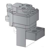
GAP
NO GAP
Loosen
Pull Back
Disconnect
1
2
3
Figure 9, Hydraulic Couplers - Unlock and Disconnect
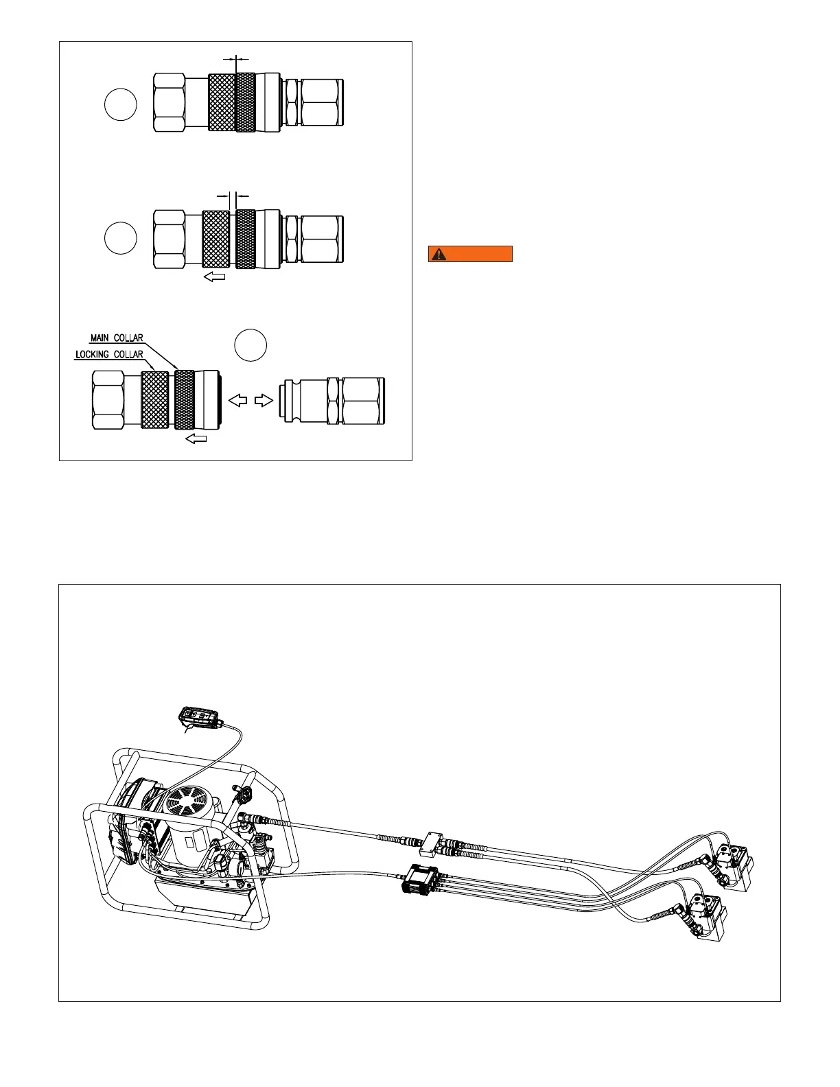
5.6 Hose and Cable Assemblies
See Figure 10 for an overall view of the hoses, cables, flow-
divider and junction box.
For detailed hose and cable connection instructions, refer to the
Smart Tensioning Pump instruction sheet (document L4186).
Before connecting or disconnecting hydraulic couplers on hoses,
tensioner, pump and other hydraulic devices:
• Be absolutely certain that any pressure is completely relieved.
Verify that both the pump hydraulic pressure gauge and the
touchscreen HMI pressure readout indicate zero (0) bar/psi.
• Be certain that the pump motor is o and that the pump control
valve is not energized
WARNING
All hoses, fittings and components used in the
system, MUST be rated at or above the maximum rated working
pressure of the tensioner - 21,750 psi [1500 bar]. Failure to
observe this instruction could result in dangerous high pressure
oil leakage. Death or serious personal injury could result if a high
pressure oil stream penetrates the skin.
5.7 Preparation for Tensioning Procedures
• Be sure all personnel involved in this procedure are trained
in tensioning procedures and in the equipment being used.
Ensure that all personnel read and understand the safety
information contained in Section 2 of this document.
• Read and completely follow the additional pump setup
instructions contained in pump instruction sheet L4186. Be
sure that the pump reservoir is filled with oil.
• Be sure all personnel are familiar with the use of the Smart
Pump and its HMI screens. Refer to the Smart Tensioning
Pump instruction sheet (document number L4186) for
additional information.
• Inspect the connecting rod studs to verify that they contain no
Figure 10, Hose and Cable Assembly
Notes:
• Refer to smart tensioner pump manual
(document No. L4186) for detailed hose and
cable connection diagrams.
• For illustrative purposes, touchscreen HMI and
chafe gear protective coverings are not shown
in this graphic.
 Loading...