12
obvious damage or defects, and that they appear capable of
withstanding the force that will be applied by the tensioners.
• Ensure that the connecting rod caps are correctly and firmly
seated, and that the nuts are fully threaded onto the studs
until they firmly contact the connecting rod cap surface.
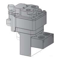
There should be a total of 26 mm [1.02 inch] above each nut.
Absolute minimum stud protrusion required to safely tension
the studs is 21 mm [0.83 inch]. See Figure 11.
26 mm
[1.02 in.]
M19 x 1.5
Figure 11, Checking Stud Protrusion
• Before installing each tensioner, be sure that the threaded
portions of the studs and puller sleeves are clean and free of
damage.
• Before using the tensioner and pump, use the pump's oil flush
feature to remove any trapped air from the system. Refer to
the pump instruction sheet (document No. L4186) for oil flush
procedure.
6.0 TENSIONING PROCEDURES
• Refer to the Caterpillar 3600 connecting rod Disassembly and
Assembly instructions (available from Caterpillar) for detailed
tensioner installation and operation procedures.
• Refer to the Smart Tensioning Pump instruction sheet
(document No. L4186) for detailed pump set-up instructions
and user-level pump troubleshooting information.
• If oil leaks occur or if abnormal operation is noticed, STOP the
pump immediately and determine the source of the problem
before resuming the tensioning procedure.
7.0 ADDITIONAL PRODUCT FEATURES
7.1 Maximum Stroke Indicator
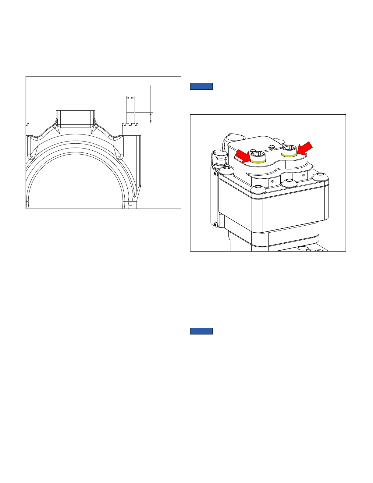
Maximum allowable tensioner stroke is visually indicated
by a yellow painted groove located on the puller sleeve’s
circumference. See Figure 12.
Continually watch for the maximum stroke indicator during
tensioning procedures. Stop pressurizing the system immediately
if the indicator becomes visible at one or both puller sleeves.
The maximum stroke indicator groove can be felt by hand. If
the view of the tensioner is restricted or obstructed, periodically
check for the groove by hand as tensioning procedures are
performed.
Reaching maximum stroke is a possible indication of a problem
with the connecting rod assembly.
If the maximum stroke indicator appears before the desired
hydraulic pressure is reached, always stop the pump and verify
that pressure is fully relieved (0 psi/bar).
Check for obvious problems, such as broken connecting rod
studs or worn threads. Also check for correct assembly of parts.
Reassemble and/or replace parts as required. Then, repeat the
tensioning process.
If the maximum stroke indicator appears before the
desired hydraulic pressure is reached, no additional load will be
transferred to the connecting rod studs, and the studs and nuts
will not be tensioned to the correct values.
Figure 12, Maximum Stroke Indicators
7.2 Over-Stroke Protection System
The tensioner contains an over-stroke protection system. This
feature helps reduce the risk of damage to both the tensioner and
the connecting rod studs.
The over-stroke protection system is activated after the maximum
stroke indicator (on either one or both puller sleeves) is fully
exposed. Oil leakage will be visible in the top cap area when
pressure relief occurs.
Clean-up any leaked or spilled oil. Dispose of this oil in
accordance with all applicable regulations and laws.
 Loading...