11
WARNING
Continuously monitor the load and be
prepared to stop the pump immediately. Never allow the
pump to operate in the latched mode while it is unattended.
When in latched mode, pump will shut o automatically
after 5 minutes if it is not stopped sooner by the operator.
Monitor the hydraulic reservoir oil level when
operating the pump in latched mode for a prolonged period of
time. Be careful not to allow the reservoir to become completely
drained of oil.
Pendant Haptic Pulse Feature
• To provide positive confirmation of pump status, the pendant
will vibrate haptic pulses as the pendant buttons are depressed
and released.
• One haptic pulse indicates that the motor has started. Two
haptic pulses indicate that the motor has stopped.
• The pendant will vibrate haptic pulses In conjunction with the
flashing LED indicator to signal when a fault code has been
triggered. Refer to Section 14.0 for additional information.
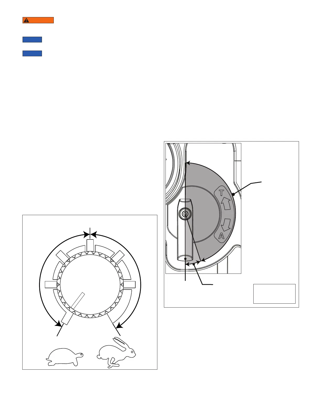
6.4 Variable Speed Control
A rotary knob mounted on the pump rear panel controls the
motor speed. See Figure 5.
The adjustable speed range is approximately 25 to 100% of full
rated output, or about 600 to 2400 RPM.
• Knob turned fully counterclockwise equals approximately
25% of rated output. This is the lowest possible setting.
• Midpoint setting of knob equals approximately 50% of rated
output.
• Knob turned fully clockwise equals 100% full rated output or
maximum possible speed as determined by the pump internal
controls, based on operating conditions.
C
o
n
s
t
a
n
t
S
p
e
e
d
M
o
d
e
C
o
n
s
t
a
n
t
P
o
w
e
r
M
o
d
e
Figure 5, Speed Control Knob
SLOW
FAST
(25%)
(50%)
6.5 Constant Speed and Constant Power Modes
• When the speed control knob is set between the full counter-
clockwise (25%) and midpoint (50%) positions, the pump
operates in constant speed mode. In this mode, the motor speed
will not automatically increase or decrease to compensate for
changes in load. The user can precisely regulate the amount
of hydraulic flow and can manually reduce the flow rate, as
needed, to provide increased control and slower movement.
• When the speed control knob is set between the mid point
(50%) and full clockwise (100%) positions, the pump operates
in constant power mode. In this mode, the pump motor will run
at the set speed until maximum power is delivered. If the load
further increases, the motor will automatically reduce speed to
maintain peak torque (and hydraulic force) under demanding
conditions.
6.6 3-Way, 2-Position Control Valve (EP3204J Models)
The control valve on EP3204J models is operated by a rotary
lever and has two positions, “A” Advance and “T” Tank (return).
It is designed for use with single-acting hydraulic cylinders and
tools. See Figure 6.
Figure 6, Control Lever Positions - EP3204J Models
TANK
(RETURN)
FLOW
METERING
RANGE
T
A
Note: Lever
positions shown
are approximate.
• The pump must be running to advance the cylinder or tool.
• Moving the lever fully to the “A” position will direct hydraulic
flow from the pump reservoir to the cylinder or tool.
• Moving the lever from the “A” position to the “T” position
will direct hydraulic flow from the cylinder or tool back to the
reservoir. This is typically done with the pump turned-o.
• If the pump is turned-o while the lever is in the “A” position,
the cylinder or tool will stop and the pump internal valving will
hold the load in most applications. However, since the pump
contains no safety locking valve, suitable blocking must be
placed immediately under the raised load.
 Loading...