9
4.0 PRODUCT DESCRIPTION
4.1 Introduction
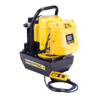
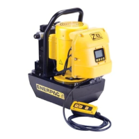
The Enerpac E-Series electric manual valve pumps are designed
for use with industrial hydraulic cylinders and tools rated at
10,000 psi [700 bar] working pressure.
Features include:
• Manual 3-way, 2-position control valve (EP3204J Models) or
manual 4-way, 3-position control valve with tandem center
(EP3404J Models).
• Remote control 2-button Smart IQ pendant with LED status
and diagnostic indicator.
• Choice of jog (momentary on) or latched (constant on)
operational modes.
• Variable speed permanent magnet direct drive motor with
unique constant power mode.
• Durable and lightweight all aluminum chassis construction.
• Two-stage pump design for fast system fills and controlled
flow at high pressures.
• Six discreet pump elements provide even flow and smooth
operation.
• Built-in user and service center diagnostic features.
Refer to Figure 2 for a diagram of the pump's major features and
components.
4.2 Conformance to National & International Standards
Enerpac declares that the E-Series pumps have been
tested and conform to applicable standards and are
approved to carry the CE, TUV C and US, and FCC
certification marks. An EU declaration of conformity is included
in the shipment.
4.3 Electromagnetic Compatibility (EMC)
Enerpac E-Series pumps have been tested and certified to
conform to CE-EMC Emission and Immunity standards and to
FCC emission standards.
5.0 PREPARATION FOR USE
5.1 Important Receiving Instructions
Visually inspect all components for shipping damage. Shipping
damage is not covered by warranty. If shipping damage is found,
notify carrier at once. The carrier is responsible for all repair and
replacement costs resulting from damage in shipment.
Note that a small amount of residual hydraulic oil may be present
within the packaging from product final assembly and testing
procedures. In addition, a small amount of hydraulic oil may
leak from the reservoir air breather (covered by a removable
absorbent pad) during shipping. A minimal amount of oil inside
the shipment should be considered as normal and not as a
cause for concern.
5.2 Hydraulic Connections
As hydraulic hoses, fittings and components are assembled,
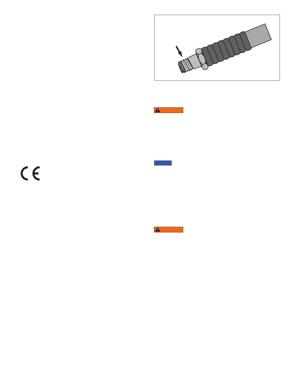
apply 1-½ wraps of PTFE thread sealing tape to all threaded
NPT or NPTF fittings, leaving the first complete thread free of
tape as shown in Figure 3. Use care to prevent pieces of tape
from entering the hydraulic system.
Figure 3, Hydraulic Sealing Tape Application
All hoses, fittings and components used with the pump must be
rated for at least 10,000 psi [700 bar] operation.
WARNING
Avoid kinking or tightly bending hoses. Do not
exceed the hose manufacturer's stated minimum bend
radius. If a hose becomes kinked or otherwise damaged, it
must be replaced. Damaged hoses may rupture at high
pressure. Serious personal injury may result.
Hydraulic hose ports are located above the oil level indicator,
to the left of the control valve lever. See Figure 2, items 20 and
22. EP3404J models contain both “A” and “B” ports. EP3204J
models contain only port “A”. Both ports have 3/8" NPTF threads.
Hydraulic fittings, couplers and hoses are user-
supplied and not included with the pump.
Make hydraulic connections as described in the following steps:
1. To prevent the pump from starting, be sure that the pump
AC power cord is disconnected from the electrical outlet.
2. Relieve any residual trapped pressure BEFORE removing
the plug(s) from the pump hydraulic ports:
• EP3204J Models only: Move the valve lever fully counter-
clockwise to the “T” position.
• EP3404J Models only: Move the valve lever several times
back and forth between the “A” and “B” positions.
WARNING
A small amount of oil leakage or spray may
occur when plug is loosened in the following step. To prevent
eye injury, keep face away from this area when plug is
loosened.
3. Remove the plug from pump port “A” and pump port “B” (if
equipped).
4. As required, install hydraulic fitting(s) or coupler(s) in the
pump port(s). Tighten until finger tight. Then tighten an
additional 1.5 to 3.0 turns or torque to 40 ft. lb [54.2 Nm].
5. Make hydraulic hose connections as described for each
model:
• EP3204J Models Only: Connect the hose from pump port “A”
to the advance/retract port of the cylinder or tool.
• EP3404J Models Only: Connect the hose from pump port “A”
to the advance port of the cylinder or tool. Connect the hose
from pump port “B” to the retract port of the cylinder or tool.
• All Models: As required, install hydraulic pressure gauges
(user-supplied) in the system. Installation of a pressure gauge
in each hydraulic line is strongly recommended.
 Loading...