22
L4627_b
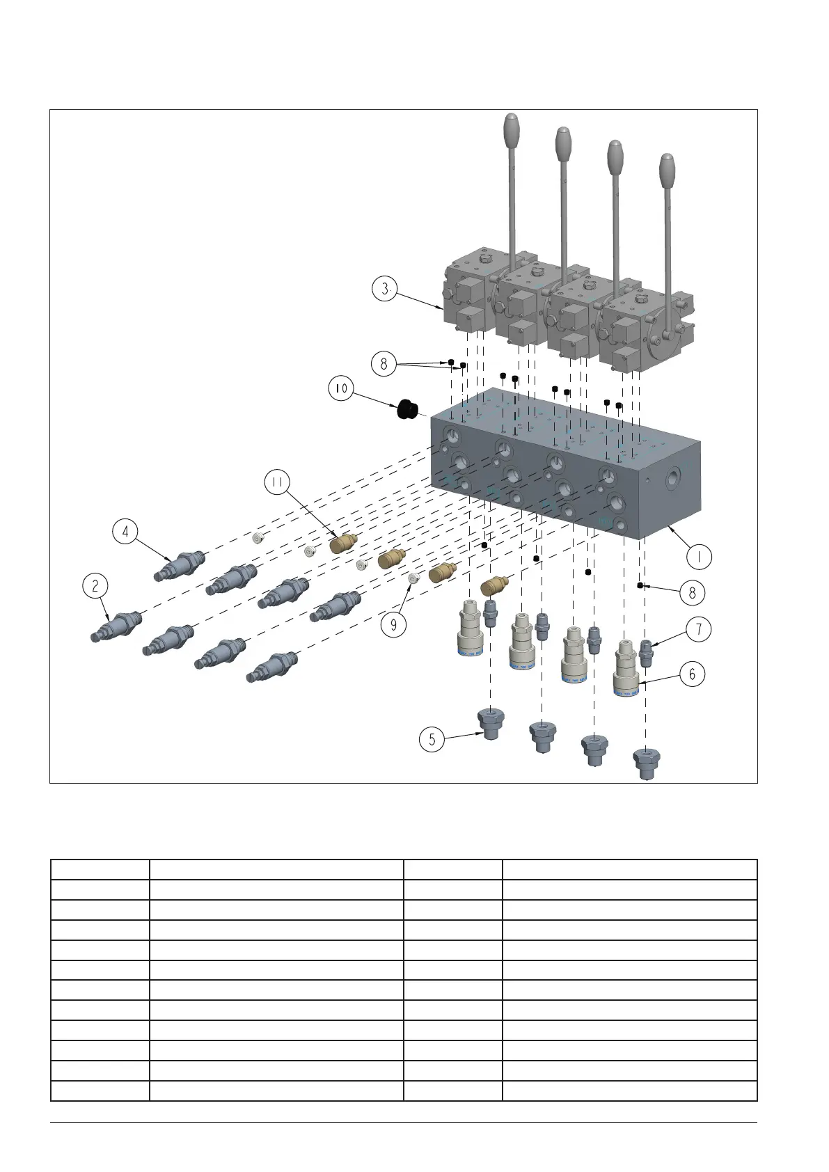
11.3 Manual HPU Manifold Assembly
Figure 20: Manual SHS manifold assembly exploded view
11.3.1 Manual HPU Manifold Assembly Table of Parts
Item N.º Description Qty. Part Number
1 Manifold 1 DB5086840A
2 Relief Valve 4 DB1062663
3 Hand Directional Valve 4/3 700 bar 4 DB1154661
4 Relief Valve 4 DB1062663-1
5 Male Coupler 4 CH604
6 Female Coupler 4 CR400
7 Fitting 4 FZ1617
8 1/16” NPT Plug 12 A1006245
9 1/8” BSP Plug 4 DB2142006
10 1/2” BSP Plug 1 DB2141006
11 Test Point Minimess, 1/4” BSP 680 bar 4 DB2421034
 Loading...