19
3940011 12.12
5.1 Control Settings
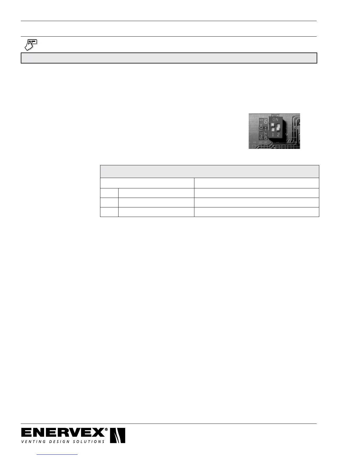
The control must be set to run in Continuous mode for this system. To do this, set dipswitch #1 to the On/Up
position. The dipswitch is located on the back of the display board inside the EBC 30 control box. See the
picture below.
5. START-UP AND CONFIGURATION
Control Settings for Negative Pressure Applications
Parameter Setting
21 Draft Set-point *To Be Determined at Start-Up
22 Exhaust Mode Continuous
262 Alarm Delay 30 Seconds
5.2 Choosing the Set-Point
Thedrafteffectsofthechimneyfanwilldecreaseasthereplacesbecomefurtherawayandthesetpointmust
besettoensureaconstant,negativepressureatthefurthestreplacefromthefan.Formostapplications,the
set-point will be between 0.05” W.C. and 0.10” W.C.
Topreventthereplaceslocatedclosetothefanfromover-drafting,adjustthestrokeoftheactuatoroneach
damper as described in Chapter 5.3.
5.3 Checking Fan Rotation (3-phase only)
Verify the fan blades are rotating clockwise. The EBC 30 can be set to run the fan at a very low
speed while doing this.
If the fan is rotating counter-clockwise, switch the phase wires connecting to terminals V and W of the VFD.