A G-TRAC MANUAL
IOM-24 Page 10 March 1999 R1
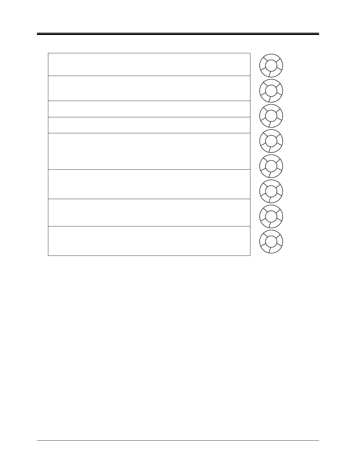
XI. POTENTIOMETERS ON THE G-TRAC
P1 DISCHARGE CALIBRATION – Factory set as required. Do not readjust
without insuring that no reset signals are affecting discharge temperature
(Page 7).
P2 ROOM RESET RATIO – This sets the amount of authority the room reset
will have on the set-points desired discharge.
1=MIN RESET ±9º 5=MAX RESET ±32º
P3 ROOM CALIBRATION – Adjust as required if a room sensor is in use.
Ensure the discharge sensor is not affecting the signal (Page 8).
P4 AUXILIARY SET POINT – This pot is not normally used. If it is in use
there will be a jumper across "SP and S" or "SP and Y"
P5 VALVE SENSITIVITY – This adjusts the strength of the signal to the
valve. As it is set to a lower number, signal strength is higher and the valve
opens further. If this is not set to a low enough number (about 3) there may
not be enough drive to open the mod valve fully. If control is from a
CTRAC2.1 and valve cannot open fully, set lower until it does.
P6 INTERNAL CONTROL BAND – This pot selects a point above and below
set point that a modification is made to the valve output signal, which causes
it to react quicker. The amount of modification is not adjustable 1=10º/5=3º.
Usual setting is 3, but when G-TRAC is controlled by CTRAC set at 4.
P7 BMS RESET RATIO – Used on building management systems only.
Position 5 = +60, 1 = +32 on 4-20 MA BMS System
Position 5 = +75, 1 = +40 on 0-10 VDC BMS System
P8 BURNER ON/OFF CONTROL BAND – This sets the points at which the
burner cycles on and off. There is no delay off. Setting this control low
increases cycling. When control is from a CTRAC, usual setting is "4", setting
1 = 2ºF deadband, setting 5 = 6ºF.
To force the unit to High fire, short the discharge sensor "Q" and "U".
To force the unit to Low fire, substitute a 1000-ohm resistor for the discharge sensor and adjust the set-
point pot to just turn the heat call light on.
Regarding the above pot settings, note the following:
Pot 5 Do not set higher then 2.5 or 3 as there may not be enough power to drive the modulating gas valve
fully open. This pot regulates the response of the valve to the G-TRAC voltage signal. Three (3) is
the normal set point. Too low a set point may result in hunting due valve movement being too great
for the amount of signal change at the internal G-TRAC amplifier. This will result in unstable
discharge temperatures due to excessive hunting.
Pot 6 Operates in conjunction with pot P5. Normal set point is 3 and the set point when the G-TRAC is
controlled by a CTRAC is 4. Setting this pot too high can result in hunting.
XII. DIAGNOSTIC LIGHTS
To simplify troubleshooting and to see what the unit is doing at the moment, there are a number of "LED"
lights.
Heat Call Light
Indicates that the discharge sensor and/or any of the reset devices wired to the G-TRAC are calling for more
heat.
4
5
3
2
1
4
5
3
2
1
4
5
3
2
1
85
95
72
64
55
4
5
3
2
1
4
5
3
2
1
4
5
3
2
1
4
5
3
2
1
 Loading...

