A G-TRAC MANUAL
IOM-24 Page 4 March 1999 R1
TE 6000 SENSOR
SENSOR
(purple and blue)
Resistance in table below
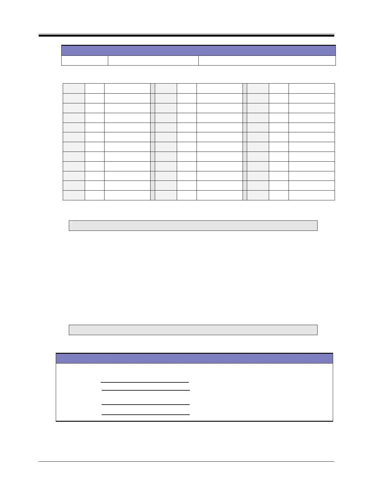
Sensor Resistance Chart for TE 6100-960 and TE 6000-960
°C °F
Resistance
°C °F
Resistance
°C °F
Resistance
-40 -40 602-605 18.3 65 983 48.9 120 1234
-34.4 -30 633 20 68 996 54.4 130 1269
-28.9 -20 665 20.6 69 1000.7 60 140 1333
-23.3 -10 698 21.1 70 1005 65.5 150 1365
-17.8 0 732 23.9 75 1026.5 71.1 160 1437
-12.2 10 768 26.7 80 1048 76.7 170 1491
-8.7 20 804 29.4 85 1070 82.2 180 1546
-1.1 30 842 32.2 90 1092 87.7 190 1602
4.4 40 881 35.6 95 1116 93.3 200 1659
10 50 921 37.8 100 1139 98.8 210 1718
12.8 55 941.5 43.3 110 1186 100 212 1778
Reference resistance is 1035 ohms at 77°F. Resistance tolerances are ±0.05 to 0.15% at 77°F. Temperature range +32 to
+104°F. (TE 6100-960 pot is 53C3, 500R, 7/8 by ¼ shaft.)
NOTE: Engineered Air’s design discharge temperature range is 30 to 140ºF.
Temperature Can Be Controlled By
DISCHARGE AIR CONTROL Consists of TE6000-960 duct sensor and set point (often
TE 6000-960) wired as above (or use the internal set point pot
4 with a jumper on “S to SP”).
DISCHARGE CONTROL WITH ROOM RESET Consists of duct sensor and set point wiring as noted
above with room sensor/set-point also connected to the G-
TRAC. (To activate this feature there must be a jumper from
terminals “RR and +”.)
Seldom used is control from a Honeywell T991A or equivalent control wired to terminals “D, U, M and V”
(R=D, W=U, B=M and V).
NOTE: To determine your system, refer to the unit wiring diagrams.
VI. RESET CONTROL
TE 6100 WIRE COLOUR C-TRAC2.1 TERMINAL PURPOSE
Room reset sensor/set-point
Blue
Z Room reset set point +
Grey
V
Room reset set point
Orange
Y Room reset centre tap
Violet
X Room sensor
In a stand-alone system the G-TRAC operates as a discharge air control. If a room-reset control is used,
the room set point and sensor will modify the set point. This is best explained by an example. The room
reset ratio authority (pot 2) setting determines high and low discharge points.
 Loading...

