A G-TRAC MANUAL
IOM-24 Page 17 March 1999 R1
Combustion Set Up
When measuring combustion, ensure probe of analyzer inserts fully in to the flue connection to the heat
exchanger. Measuring at the flue outlet may be a diluted reading due to air mixing into the flue.
High Fire Combustion Set Up
Turn unit off. Remove wires at RBW terminals on (V9055) gas valve. Connect Q209 pot to gas valve. Turn
unit back on. After unit lights off adjust Q209 to maximum fire. Ensure adequate inlet fuel pressure.
Adjust high fire manifold pressure to that listed on the rating plate. Adjust combustion air inlet damper
until high fire O
2
reading is between 3.5% and 4%. Mark high fire location on combustion air inlet damper.
Low Fire Combustion Set Up
Remove Q209 (used in above step). Attach G-TRAC wiring from terminals RBW to gas valve. Adjust
discharge temperature pot or control to just bring heat light on. After unit lights off, adjust minimum
position pot on gas valve so the burner has a complete flame around its ring. (Unit could be clocked for low
fire gas). Adjust air inlet damper until low fire. O
2
reading is between 10.5 – 11.0%.
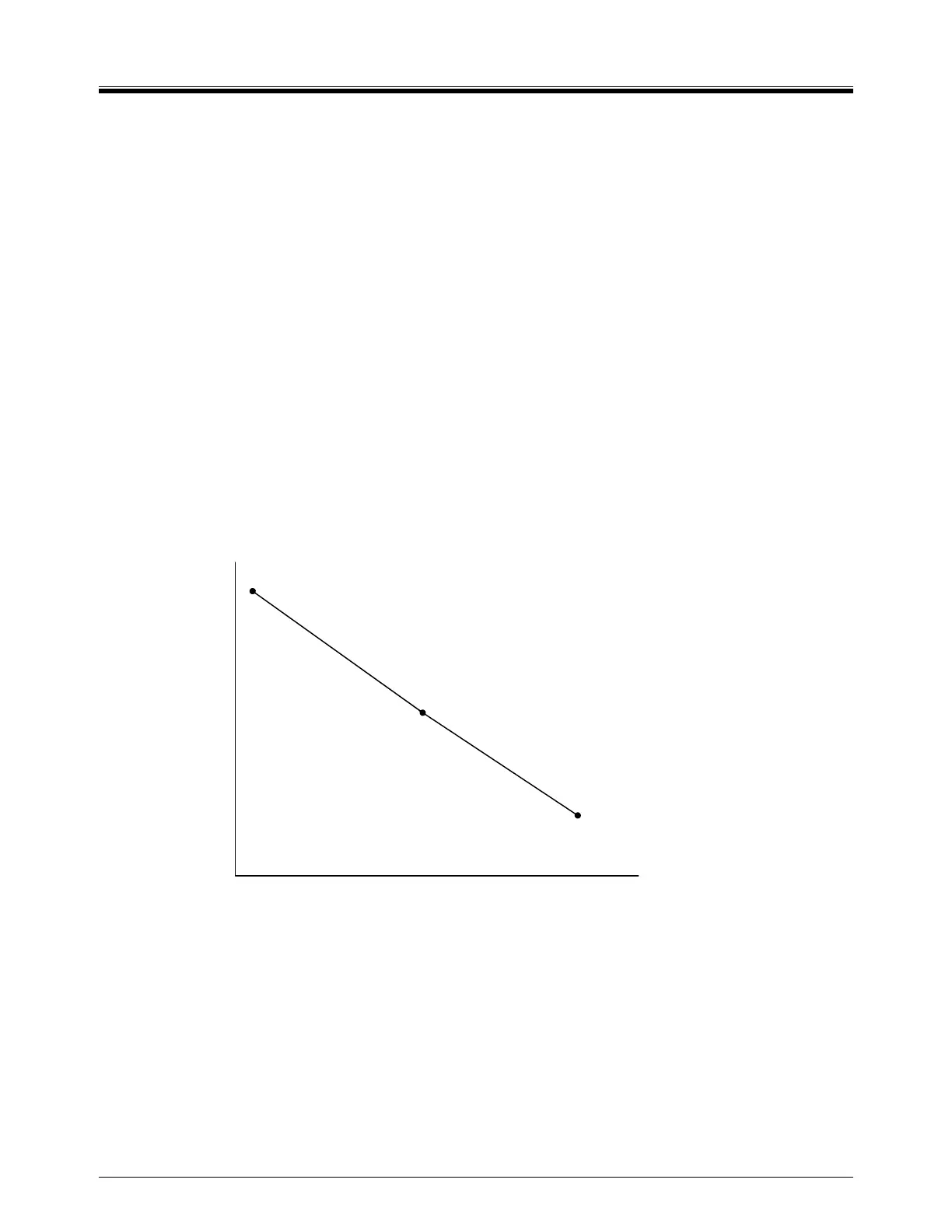
Mid-Fire Range Combustion Set Up
Reattach Q209 as instructed in high fire instructions above. After light off, ensure O
2
reading is close to
graph below. Adjust Q209 stopping at 6 – 10 positions to check combustion products. Ideally it should
follow as close to possible the graph below, however, due to gas valve/air damper curves it will not be a
straight line. Ensure that at no time the O
2
falls below 2.5% or go above 11% O
2
.
11%
6.0
3.5
Low Fire Mid Fire High Fire
O
2
 Loading...

