A G-TRAC MANUAL
IOM-24 Page 5 March 1999 R1
Example 1
Discharge Room Room Reset High Discharge Low Discharge
Set point
Set-point
Ratio (Pot 2)
Room Call Max Room Call Min
70ºF
72°F
Pos 3 = 14
84°F 56°F
As the room temperature deviates from 72ºF it can modify the discharge temperatures up to as high as
84ºF and as low as 56ºF.
Example 2
Discharge Room Room Reset High Discharge Low Discharge
Set point
Set-point
Ratio (pot 2)
Room Call Max Room Call Min
55ºF
72°F Pos 3 = + 14
69°F 41°F
As the room temperature deviates from 72°F it can modify the discharge temperature up to as high as 69°F
and as low as 41°F. Note you cannot reach a 72° room temperature. Also note that the internal design of
the
G-TRAC will resist dropping the discharge temperature below 52°F.
Example 3
Discharge Room Room Reset High Discharge Low Discharge
Set point
Set-point
Ratio (pot 2)
Room Call Max Room Call Min
63ºF
72°F Pos 4 + 18
81°F 45°F
This will allow discharge temperature as high as 81°F. If the room set point were turned up to 76°F we
would reset discharge to 81°F until the space temperature was raised to about 76°F. Also note that the
internal design of the
G-TRAC will resist dropping the discharge temperature below 52°F.
NOTE: When dealing with systems that are equipped with room reset controls be aware
that any room sensor must be located in an area where it is sensing a true
average space temperature. A room reset that is located in a hot or cool area that
does not represent the room temperature will create room comfort problems. Also
do not locate the reset sensor in an area that is affected by discharge air from any
duct or other device. The G-TRAC terminals "RR and +" need to be jumped when
when the room reset is used. Note that on some wiring diagrams this may be
jumped during one mode and inactive in another.
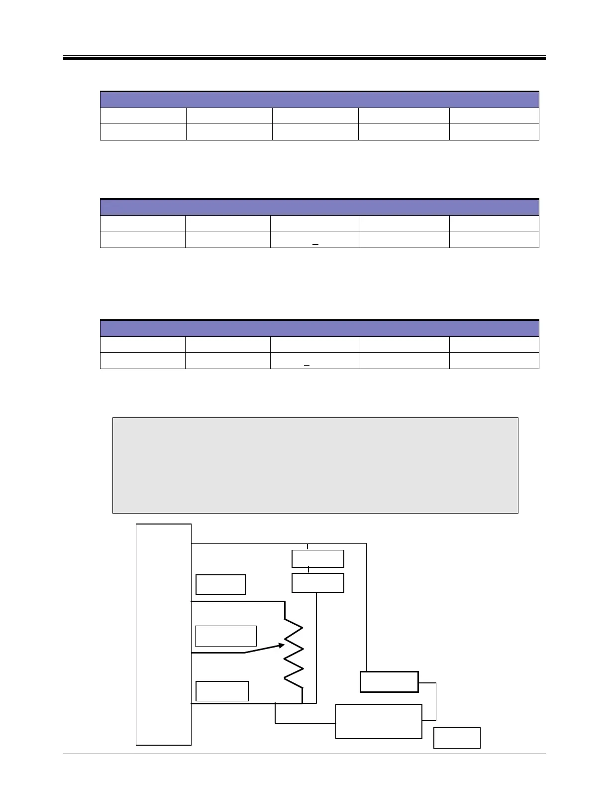
TE
TE6000
Grey
X
V
Orange
Blue
Built in
TE6100
TE6000
Violet
 Loading...

