A G-TRAC MANUAL
IOM-24 Page 3 March 1999 R1
V. MASTER SET-POINT
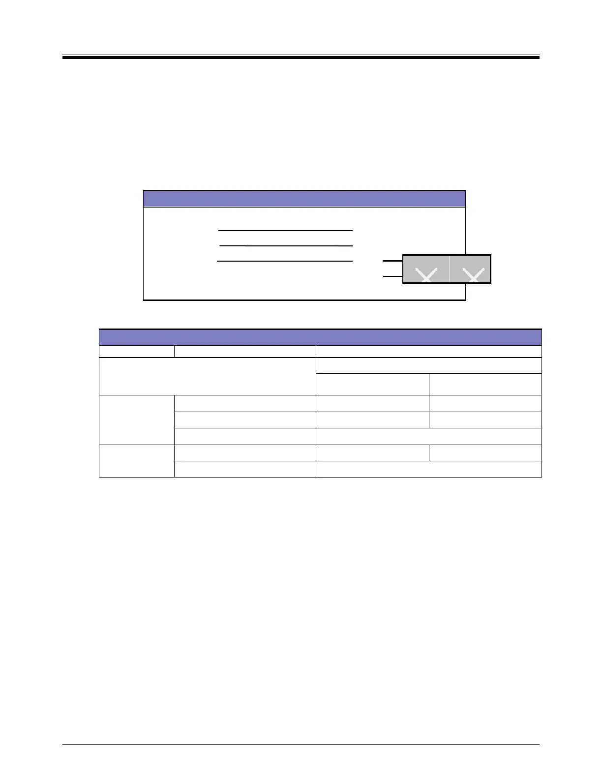
TE 6100 Wiring Connections and Resistance Values
As a SET POINT, the G-TRAC is designed to use either:
The set point pot 4 (auxillary setpoint) (range of 12-35°C or 55-95°F). If the G-TRAC pot 4 auxillary set-point
is used, terminals “SP and S” must be jumped, or;
The Johnson TE 6100-960 set point (range of 50-85°F and often remote mounted). If the TE 6100-960 is
used as a set-point, “S to SP” must not be jumpered and the TE 6100 must be wired:
TE 6100 Wires CTRAC2.1 Terminals
Violet (not used, sensor)
Blue U
Orange S
Grey M
Red (not used) Q
(No jumper S-SP)
TE6100-960 Sensor/Set Point
SENSOR (purple and blue) Same resistance as TE 6000-960
Set-Point Dialled To
60 degrees 90 degrees
POT
(orange and grey)
2.725 K 3.272 K
(orange and blue)
3.184 K 2.702 K
(blue and grey) 970
OTHER
(purple and orange)
4.19 K 3.71 K
(purple and grey)
About 1.981 K (varies with element temp.)
TE 6000 Sensor
 Loading...

