Do you have a question about the Engcon EC204 and is the answer not in the manual?
Provides general information about the user manual and its purpose.
Guidelines for environmentally responsible disposal of materials.
Instructions for handling and storing the tiltrotator safely.
Specifies temperature ranges for operation and storage.
General safety advice and explanation of warning levels.
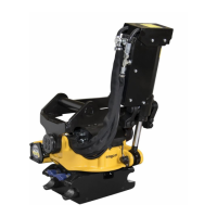
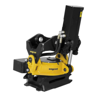
Overview of the tiltrotator's flexibility and efficiency.
Information on compatible tools for use with the tiltrotator.
Details about the Q-Safe warning system for tool connection.
Diagram and component identification for the Q-Safe system.
Monitors quick hitch status and provides alarms.
Diagram and component identification for HS/SW quick hitch.
System for efficient hydraulic tool changes without leaving the cab.
ePS rotation sensor for excavator guidance system.
Diagram and component identification for ePS/C2C.
Information on the hydraulic oil used and compatibility requirements.
How to check the product's rating plate against the EC Declaration.
Instructions for the mechanical attachment of the tiltrotator.
Step-by-step guide for mounting the tiltrotator.
Guidance on electrical and hydraulic hose installation.
Specific installation instructions for the Q-Safe system.
Final checks and function testing after installation.
Safety precautions and guidelines for operating the tiltrotator.
Approved and not approved lifting points for safe operation.
Specific usage instructions and warnings for the integrated grab.
Notes on increased wear when using hydraulic hammers.
Considerations for using augers and avoiding overheating.
Requirements and precautions when using pallet forks.
Restrictions on using the tiltrotator with a crane boom.
Operating the tiltrotator with different control systems.
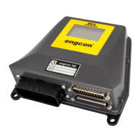
Operation of the DC2 control system.
Operation of control system 10.
Operation of control system 9-2.
Operation of control system 1.
Operation of control system 15.
Operation of SQ/QSC quick hitch lock systems.
General procedure for connecting and disconnecting tools.
Steps for connecting tools using hydraulic locks.
Steps for disconnecting tools using hydraulic locks.
Steps for connecting tools using mechanical locks.
Steps for disconnecting tools using mechanical locks.
Guidance on fitting and configuring quick hitch locks.
Overview of maintenance intervals and user-performed tasks.
Checklist and procedures for daily inspections.
Procedures for cleaning and replacing face seals.
Specific maintenance for the EC-Oil system, including cleaning.
Lubrication schedule and recommendations for the tiltrotator.
Detailed instructions for manual and automatic tiltrotator lubrication.
Procedure for greasing quick hitch components.
Lubrication points for integrated grab models GR10 and GR20.
Lubrication points for integrated grab model GR20RR.
Operator checks and service tasks every 250 hours.
Procedure for shimming the tilt upper section.
Methods for checking axial and radial play in the tiltrotator.
Procedure for measuring and checking lateral play.
Procedure for measuring and checking rotational play.
Checking the condition and wear of thrust washers.
Explains the impact of rotation play on the tiltrotator.
Calibration requirements for the ePS rotation sensor.
Specifications for torque tightening various fasteners.
Troubleshooting the Q-Safe system based on indicator signals.
Table of Q-Safe indicator behaviours and their meanings.
Troubleshooting the HS/SW quick hitch with sensor.
Table of HS/SW indicator behaviours and their meanings.
Troubleshooting the ePS/C2C system.
Table of ePS/C2C indicator behaviours and their meanings.
Guidelines for the placement of decals and warning signs.
Specific decal information for control systems 9 and 10.
Information about warning decals and their locations.
Details on warning decals located inside the operator's cab.
Specific warning decal 9000160 for cab placement.
Details on warning decals located on the product itself.
Specific warning decal 980101 for product placement.
Specific warning decal 9000338 for product placement.
Explanation of symbols used in warning decals.
Technical specifications and dimensions for the tiltrotator models.
Technical specifications for integrated grab cassettes.
Torque specifications for load-holding valves on tilt cylinders.
Definitions of terms and acronyms used in the manual.
Diagram and list of tiltrotator components with numerical designations.
Recommended service intervals and tasks for specialists and operators.
Guidance on documenting service actions and maintenance history.
| Brand | Engcon |
|---|---|
| Model | EC204 |
| Category | Industrial Equipment |
| Language | English |