Do you have a question about the Engcon DC2 QSC and is the answer not in the manual?
General information about the user manual's content and purpose.
Guidelines for environmentally responsible disposal of product components.
Information on how to obtain support and order replacement parts.
Details on the control system's compliance with directives and standards.
Explanation of warning levels (DANGER, WARNING, CAUTION, IMPORTANT) used in the manual.
Overview of safety functions and risks managed by the QSC system.
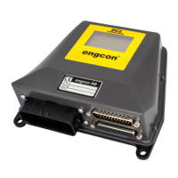
Description of the DC2 proportional control system and its capabilities.
Visual representations and meanings of control symbols used in the system.
Explanation of symbols and button functions on the QPM control panel.
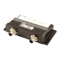
Overview of the QLM module's components and function.
Diagrams illustrating system components for different control types.
Guide to navigating the cabin module's menu structure and options.
Details on identifying the product using part and serial numbers.
Instructions on how to access and log into the system menu.
Overview of the main menu options: User, Joystick, System, Tool.
Information on selecting and managing user profiles and settings.
Calibration procedures for joystick grips and thumbwheels.
Options for system backup and data management.
Functions for selecting and editing tool configurations.
How to select and cycle through available tool profiles.
Options for editing parameters like rotation and tilt for selected tools.
Display of rotation speed and ramp settings for a tool.
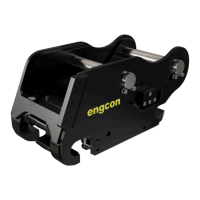
Detailed instructions for connecting and disconnecting tools using the quick hitch.
Step-by-step guide for connecting tools with hydraulic lock.
Procedure for opening the quick hitch to attach a tool.
Step-by-step guide for disconnecting tools with hydraulic lock.
Procedure to open the quick hitch for tool disconnection.
Information on configuring slew and lift limitations for the tiltrotator.
Instructions for activating and operating wheel control.
Instructions for activating and operating track control.
Procedure for switching between user profiles and settings.
Guide to downloading the necessary software for system configuration.
Instructions for connecting the system to a computer via USB or Bluetooth.
Overview of the DC2 Android application's interface and features.
Explanation of the main screen elements and icons in the app.
Steps to activate Bluetooth and pair a smartphone with the system.
How to access system information and troubleshooting data via the app.
Information on managing tool settings and profiles within the app.
Procedure for calibrating joystick grips and thumbwheels using the app.
How to switch between different user profiles in the application.
Using the app to view alarm logs and diagnose system faults.
Overview of remote support capabilities via smartphone or PC.
Steps to initiate remote support by contacting personnel.
Procedure for disconnecting the smartphone from the system.
Recommendation for applying electrical compound to protect contacts from corrosion.
Table detailing symbols, indications, descriptions, and actions for QPM alarms.
Details on indications and behaviour of the QLM module.
Explanation of LED indicators and their meanings for the QLM module.
Description of audible alarms and sensor monitoring for faults.
Details on QCM module LEDs, outputs, and their functions.
Diagrams and numbering for the MIG2 grip decals.
Decal layout for part number 841869.
Decal layout for part number 1047518.
Decal layout for part number 9000229, including symbol descriptions.
Detailed explanation of the symbols used on the 9000229 decal sheet.
Steps to activate double-acting function using 9000229 decals.
Steps to activate tiltrotator control using 9000229 decals.
Decal layout for part number 9000230, showing various functions.
Detailed explanation of symbols on the 9000230 decal sheet.
Steps to activate double-acting function using 9000230 decals.
Steps to activate tiltrotator control using 9000230 decals.
Decal layout for part number 9000258, including activation steps.
Steps to activate double-acting function using 9000258 decals.
Steps to activate tiltrotator control using 9000258 decals.
Decal layout for part number 9000259, showing activation steps.
Steps to activate double-acting function using 9000259 decals.
Steps to activate tiltrotator control using 9000259 decals.
Decal layout for part number 9000268, showing DC2 functions.
Decals for activating and deactivating track control.
Decals for activating and deactivating wheel control.
Decal for wheel control activation/deactivation.
Warning decal for maximum speed in wheel control.
Diagrams for activating double-acting function and tiltrotator control.
Visual guide for activating double-acting and tiltrotator functions.
Decals and steps for activating double-acting and tiltrotator controls.
Definitions of key terms used in the manual, such as Base machine, Decal, Grip.
List of abbreviations and their meanings (CM, EC, TM, QSC, etc.).
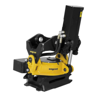
| Category | Tiltrotator |
|---|---|
| Suitable for | Excavators |
| Control System | Proportional control |
| Tilt Angle | 45° |
| Compatibility | Excavators |
| Maximum Load Capacity | Varies depending on the tiltrotator model |
| Weight | Varies depending on the tiltrotator model |
| Hose Length | Varies depending on installation |