Page 6
Omniguard Cellular™ Owner’s Manual
Page 7
Engineering Solutions Inc
Section 3: Quick Setup & Usage
This section is a quick reference for using your Omniguard.
1. Find a safe place for the Omniguard outside the containment area.
Plug the power cord into an AC power outlet.
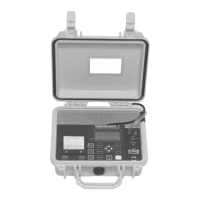
2. Connect one end of tubin
g to
the nozzle.
Secure the other end
of pressure tubing inside the containment area
.
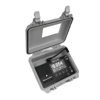
3. Press the button to turn on the Omniguard.
4. A quick start tutorial will explain how to use the touchscreen. Touch
anywhere on the screen to go to tutorial screen 2. Touch the
icon to exit the tutorial and go to the Home screen.
5. To get a printed copy of the Job Log, touch the
icon.
6. Touch START JOB at the bottom of the screen to begin a new
job. On the next screen, confirm Start New Job and enter a job
name, then touch the
icon.
7. Check Alarm 1 & 2 settings by touching the Alarm settings
displayed on the Home screen. Adjust as needed by touching the
arrows to change the value up or down.
8. On any screen touch
to get help about that screen. Touch
again to go to the general Help menu.
Once a job has been started, the status will indicate WAITING FOR
PRESSURE until containment pressure reaches the normal operating
window (a pressure reading that is between the Alarm settings). When
reached, the status will change to NORMAL and a green border will
appear indicating that the Omniguard is now in its normal operation
mode. The logging & printing pressure readings begins when the
NORMAL status is achieved.
During normal operation, the highest and lowest pressure readings
will be logged into memory and printed with a time/date stamp every
15 minutes (the default Normal Operation Log Rate).
If the monitored pressure then goes outside the operating window,
the unit will go into alarm mode. The alarm will sound, the status will
change to >>ALARM<< and a red border will appear on the screen.
The log and print rate of the pressure readings will increase to every
15 seconds (the default Alarm Condition Log rate).
To mute t he alarm d uring an a larm condit ion, touch t he
icon once.
The icon will change to
and the alarm will remain muted until the
alarm condition is over.
Power On/Off
Inlet Nozzles
Ambient (Reference)
Containment
Front Panel Icons
USB Port Status Icons
Analyzing
device.
USB Flash Drive
connected.
USB Flash Drive error -
full or write protected.
Connected to PC
USB Port Adapter
connected.
Screen Icons
Touch for item specific
Help. Touch again for
Help menu.
Touch to arm or disarm the
audible alarm - mutes during
an Alarm condition.
Touch to exit or return
to previous screen.
Touch for
Alarm settings.
Touch f or Main Me nu.
Touch to scroll thru menu,
Job Logs, reports or Help.
Indicates the battery
life remaining &
charging status.
Monitoring Status:
Printer On
Printer Off
Printer Off
(battery powered)
Touch for Printer settings.
Paper Jam
START JOB
WAITING FOR PRESSURE
NORMAL
APPROACHING ALARM
ALARM
Network Communication Settings Icons
Cellular Modem connected.
Cellular Modem error - not
activated or network not
detected.
Cellular Modem off.
WiFi connected
with full signal
WiFi error - can not
connect to wifi network
WiFi ON - No Wifi
log in informaiton, or
no signal in range