Installation
Installation and Operation Manual - ENSITU
®
7000
8 Doc.-ID: ENS_13062019-EN
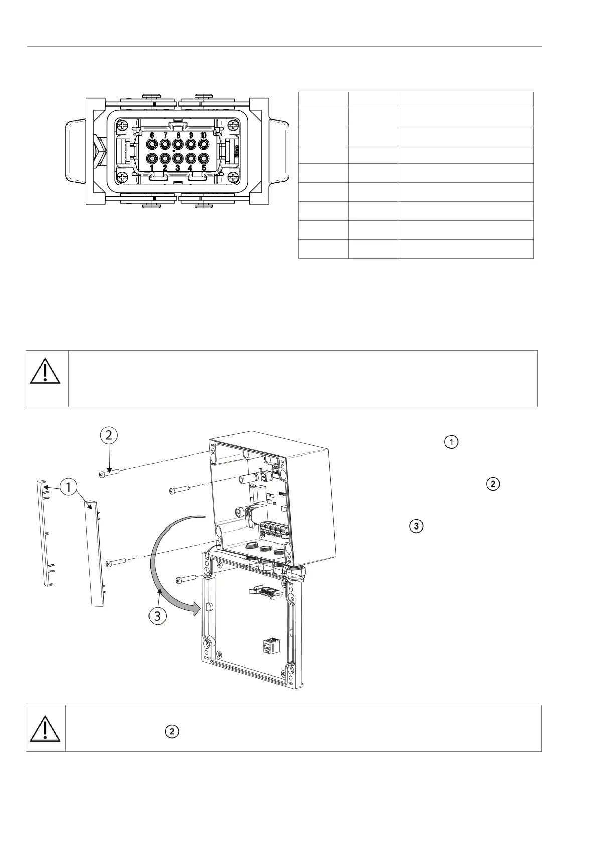
2.4 Connection of the probe plug for detached electronics
Contact Polarity Description
1, 2
+ Probe heater
3
+ Probe data board
4
+ Thermocouple
5
+ O
2
sensor
6, 7
-
Probe heater
8
-
Probe data board
9
-
Thermocouple
10
-
O
2
sensor
Figure 6 - Probe plug connection for detached electronics.
See Figure 2 for configuration and chapter 0 for cable specifications.
2.5 Access to the Terminals
Warning
Power supply lines are to be connected / disconnected only in a de-energized state as not to
risk a short circuit.
Remove the 2 clips at the sides of
the terminal box,
loosen the 4 captive screws ,
open the constrained terminal box lid
from the top .
Figure 7 - Access to the Terminals
Warning
Tighten the screws for the terminal box lid with a torque of 3 Nm.
 Loading...