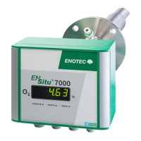
Installation and Operation Manual - ENSITU
®
7000 Table of Contents
Doc.-ID: ENS_13062019-EN 1
Table of Contents
1 System Description 2
1.1 System Overview ................................. 2
1.2 Measuring Principle .............................. 4
1.3 Intended use ......................................... 4
1.4 Safety Hazards ..................................... 4
1.5 Disruption of the Process ..................... 5
1.6 Storage instructions .............................. 5
1.7 Name Plates ......................................... 5
2 Installation 6
2.1 Installation of the probe ........................ 6
2.2 Adjusting the V-shield ........................... 7
2.3 Mounting of the Probe .......................... 7
2.4 Connection of the probe plug for
detached electronics ............................ 8
2.5 Access to the Terminals ....................... 8
2.6 Wiring Diagram of the Electronic Unit .. 9
2.7 Test gas connection / reference air ports
........................................................... 10
3 Software and Analyzer Control 11
3.1 Installation of the ENOTEC Remote App
........................................................... 11
3.2 Establish a connection ....................... 12
3.2.1 Search for available analyzers ........... 12
3.2.2 Pair with the Analyzer ......................... 12
3.2.3 Connect with the ENSITU 7000
®
Analyzer ............................................. 13
3.2.4 Enter the Pin Code ............................. 14
3.3 Screen Overview ................................ 14
3.4 Change access level .......................... 15
3.5 Save and Share System Protocols ..... 15
3.6 O
2
Sensor Calibration ......................... 16
4 Initial Operation 17
4.1 Checklist before start-up of the Analyzer
........................................................... 17
4.2 System power up ................................ 17
4.3 Display and LEDs ............................... 17
5 Service and Maintenance 18
5.1 Preparation of the test gas tubing ...... 18
5.2 Connect the test gas tube .................. 18
5.3 Test air / test gas supply to the probe for
calibration ........................................... 18
5.3.1 Test air supply with pump ................... 18
5.3.2 Test air supply with instrument air ...... 19
5.3.3 Test gas / Test air supply (certified test
gas) .................................................... 19
5.4 Exchange fuses ................................... 19
5.5 Exchange of the probe inner part ........ 20
5.6 Replacing the Filter ............................. 21
5.6.1 Remove the old Filter .......................... 21
5.6.2 Cement in the new Filter ..................... 21
6 Error Codes 22
7 Troubleshooting 24
A Technical Specifications 25
A.1 Technical specifications - KES-700X . 25
A.2 Technical Specifications - Electronics
unit ...................................................... 26
A.3 Technical Specifications - General ..... 26
A.4 Technical Specifications ...................... 27
B Dimensional Drawings 28
B.1 Dimensional drawings of the KES-700X
probes ................................................. 28
B.2 Counter flange ADP-7000 ................... 29
B.3 KES-700X Probe inner parts ............... 30
C Spare Parts 31
C.1 Probe components .............................. 31
D Warranty 32
Index 33

 Loading...