Installation
Installation and Operation Manual - ENSITU
®
7000
6 Doc.-ID: ENS_13062019-EN
2 Installation
Warning
The system is not equipped with an external power-off switch. The line voltage
switch/fuse/breaker must be installed and be in accordance with local technical standards and
should be near to the electronic unit and must be clearly marked as such. Before removal of the
electronic terminal cover the line voltage must be switched off. The line voltage to the electronic
unit must be switched on again after the cover is back in position. After installation power
conducting parts may not be accessible.
2.1 Installation of the probe
The flue gas temperature, pressure and all other process conditions must be in accordance with
the specification. Leave enough space for insertion/removal of the probe.
Before cutting a hole in the flue gas duct, make sure that the inside of the duct has enough
space for probe installation and that no fly ash is blown out nearby or any obstacles are in the
way.
ENOTEC recommends installing the probe horizontally (-3 ° to - 5 °) for fastest possible
response times.
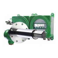
Transmitter probe
Maintain ambient and process temperature
limits.
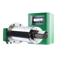
Probe with detached electronics
Maintain ambient and process temperature limits
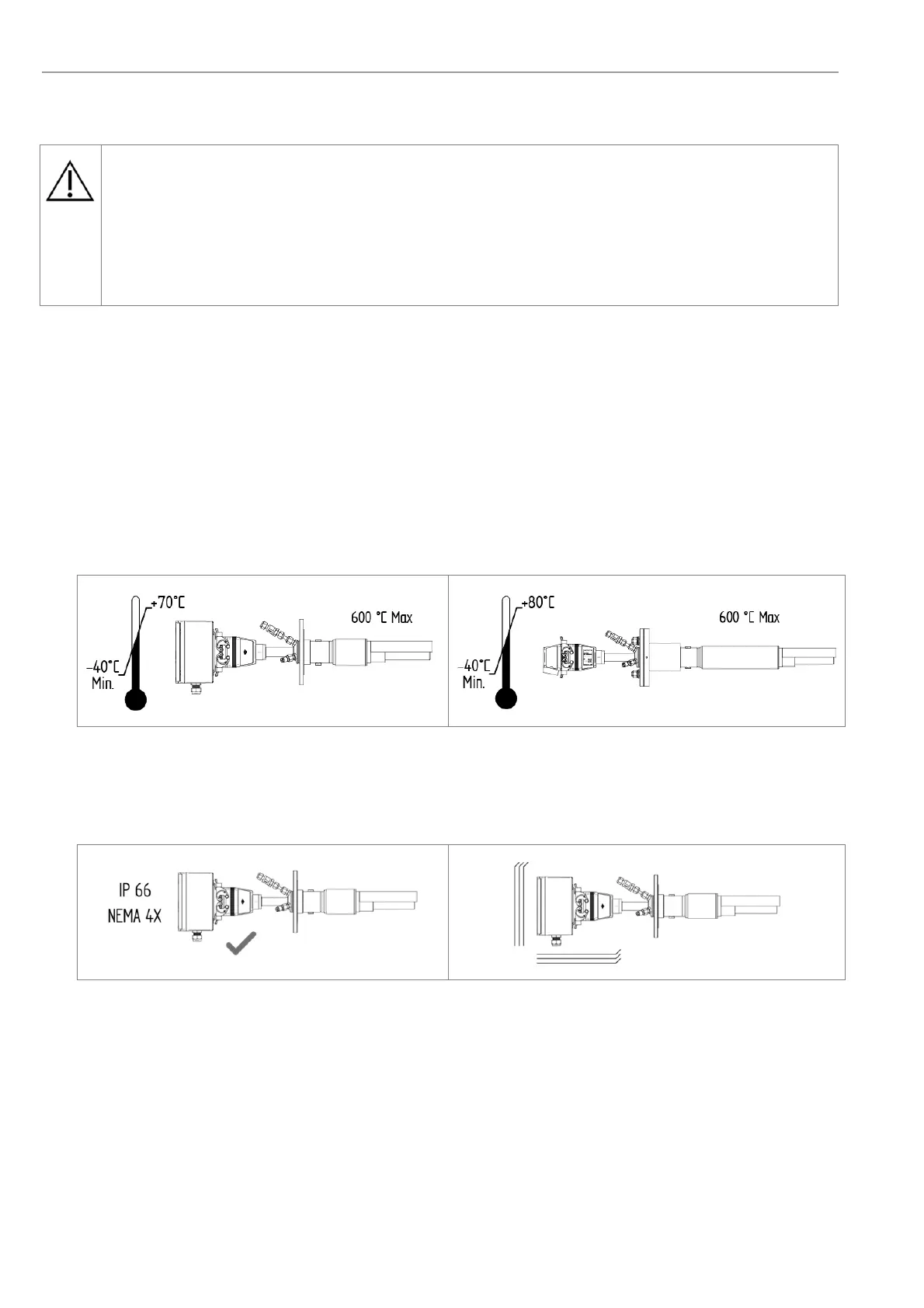
Maintain the protection class
Avoid vibrations > 2g

 Loading...