INSTALLATION — Part 2
This section is applicable for Enphase Energy System sites with an IQ System
Controller 3/3G and/or IQ Battery 5P installed.
Use Enphase tray cables (TC) and headers for control wiring. Enphase
cables are certied under UL-1277,UL-3003 and UL-83.
Enphase SKU for control cable: CTRL-SC3-NA-01.
NOTE: Enphase has validated performance using the Enphase control ca-
ble (SKU: CTRL-SC3-NA-01). Enphase cannot guarantee performance when
a third-party control cable is used.
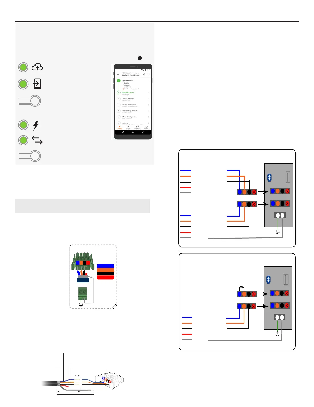
A ) Planning the wiring
The control wiring has three basic components :
•
The signal wires (blue, orange, black, red) within the control cable.
•
The Drain cable of the shield (Marked as DRAIN in Figure shown
alongside).
•
Termination resistor.
B ) Conrm if IQ Combiner is the terminal node.
If the IQ Combiner is a terminal node, leave the termination resistor
installed on the upper CTRL header. If the IQ Combiner is not the termi-
nal node, remove the termination resistor to prepare the Control header
for wiring to another node.
C ) Strip the cables for the connection
If the IQ Combiner is a terminating node of the control network, only
one wire enters the IQ Combiner through the conduit. This lands on
the lower CTRL header. The other CTRL header is terminated using
the pre-installed termination resistor.
F ) Connecting the CTRL wires to the CTRL headers
•
Connect the CTRL L (blue) to port 1 on the CTRL header.
•
Connect the CTRL H (orange) to port 2 on the CTRL header.
•
Connect the CTRL G (black) to port 3 on the CTRL header.
•
Trim the NA(red) wire.
•
Terminate the drain wire only on one end of the cable (do NOT
terminate both ends). If the terminating end is on the IQ Combiner,
connect it to the shield header on the control board below the control
headers.
IQ Gateway display and controls
Network communications LED
Green when IQ Gateway is connected
to Enphase Installer Platform.
AP mode LED
Green when IQ Gateway’s AP Wi-Fi
network is available.
AP mode button
Press to enable IQ Gateway’s AP mode
for connecting with a mobile device.
Hold for 5 seconds to start WPS
connection to a router.
Power production LED
Green when microinverters are
producing power.
Device communications LED
Green when devices are
communicating with IQ Gateway.
Device scan button
Press to start/stop 15 minute scan for
devices over the power line.
Track system installation progress with the Enphase Installer App version
3.X mobile app. The LEDs on the IQ Gateway PCB are solid green when a
function is enabled or performing as expected, ashing when an operation
is in progress, or solid red when troubleshooting with Enphase Installer
App is required. For a legend of all LED states, see Troubleshooting
a
.
Enphase Installer
App
The information contained in this document is the
proprietary and confidential information of ENPHASE
ENERGY, Inc.. You will not provide, make available
or disclose (or use for any purpose other than that
contemplated by this document) any such information
to any other party without the express, written consent
of ENPHASE ENERGY, Inc.
01
02
REVISIONS
REV DESCRIPTION CHKD DATE
ECO-006239 - INITIAL RELEASE
NOTES:
1. MATERIAL: 3M 7871 POLYESTER BASE MATERIAL,
3M ADHESIVE - 350 HIGH BONDING ACRYLIC ADHESIVE WITH CLEAR OVERLAY ON FRONT.
2. BACKGROUND COLOUR: WHITE, CONTENT COLOUR : CMYK. FOLLOW .ai FILE FOR LABEL PRINTING.
3. USE UV RESISTANT INK
4. COMPLETED LABELS TO BE PACKAGED WITH PART NUMBER AND REVISION, MFG CODE AND DATE.
5. SUBMIT ALL ARTWORK PROOFS FOR APPROVAL PRIOR TO PRINTING.
6. LABEL MUST BE UL RECOGNIZED (PGDQ2) AND CSA ACCEPTED AS SUITABLE FOR OUTDOOR USE AT
TEMPERATURES FROM -40°C TO +65°C AND SUITABLE FOR THE SURFACE TO BE APPLIED (PER UL RECOGNIZED
COMPONENT DIRECTORY). EACH LABEL MUST BE MARKED WITH VENDOR’S MARK AS DEFINED IN THE CSA LIST OF
ACCEPTED ADHESIVE-TYPE NAMEPLATES. THE SMALLEST SHIPPING PACKAGE MUST BE MARKED WITH SUPPLIER’S
NAME AND UL DESIGNATION.
7. FINISHED PART MUST BE ROHS COMPLIANT (EU ROHS DIRECTIVE 2015/863/EU). MANUFACTURER WILL BE
REQUIRED TO CERTIFY ROHS COMPLIANCE. IF THERE IS A CONFLICT BETWEEN THE SPECIFICATIONS AND
ROHS COMPLIANCE, THE VENDOR MUST CONTACT ENPHASE FOR CLARIFICATION.
8. ALL DIMENSIONS ARE IN MILLIMETERS.
780-01014
1 1
05
SIZE
SHEET OF
REVDRAWING NO.
DWN BY
ENGR
MFG
TITLE
THIRD ANGLE PROJECTION
3D MODEL
APPROVALS
DATE
C (A2)
DO NOT SCALE THIS DRAWING
ADITYA NATU
30-MAR-23
30-MAR-23
ADITYA NATU
HW
RP
06-MAY-22
02-NOV-22
03
AKC 13-DEC-22
Wiring Diagram Label,
AC IQ Combiner Box 5C
04 AKC 10-JAN-23
1 2 3
4
NA
AKC
30-MAR-23
05
ONLY FOR REFERENCE
Colour Pantone Colour Code
COOL GREY 1C
COOL GREY 3C
PANTONE 266 C
PANTONE 725 C
PANTONE 2252 C
05
1
1
2
2
3
3
4
4
NA
NA
IQ Gateway
1 2 3 4
NO
Ref
Common
C
Digital Input Relay
PD, B300
OVC II
L1 L2
L3
N
CU, 75C, 14AWG MIN
MEAS CAT III
OVC III
RECOMMENDED ROUTING
FOR ETHERNET CABLE
230+/-0.3
CUT LINE MEASUREMENT
LOAD CENTER
AC
NEUTRAL
MAIN
LUG
PV CT
GRID-TIED SYSTEMS
IQ Gateway
1 2 3 4
NO
Ref
Common
C
Digital Input Relay
PD, B300
OVC II
L1 L2
N
CU, 75C, 14AWG MIN
MEAS CAT III
OVC III
LOAD CENTER
L1 L2
TO MAIN LOAD CENTER/
IQ SYSTEM CONTROLLER/
IQ BATTERY 5P
TO MAIN LOAD CENTER
AC
NEUTRAL
MAIN
LUG
TO PV
TO PV
PV CT
GRID-FORMING SYSTEMS
380+/-0.3
To IQ System
Controller 3/3G
WARNING:
- IQ8 Grid-Tied Systems: IQ Gateway must be
powered from IQ Combiner’s Breaker
- IQ8 Grid-forming Systems: IQ Gateway must
be powered from IQ System controller
1
2
3
4
1
2
3
4
5
5
L3
1
1
2
2
3
3
4
4
NA
NA
1
1
2
2
3
3
4
1 2 3
4
4
CTRL L (BLUE)
CTRL H (ORANGE)
CTRL G (BLACK)
NA
DRAIN
CTRL L (BLUE)
CTRL H (ORANGE)
CTRL G (BLACK)
NA
DRAIN
1
1
2
2
3
3
4
1 2 3
4
1 2 3
4
4
Terminating node: CTRL (CONTROL) wiring
CTRL L (BLUE)
CTRL H (ORANGE)
CTRL G (BLACK)
NA
DRAIN
NA
NA
NA
NA
NA
NA
NA
IQ Combiner LED & buttons quick reference guide
AP mode button
Only used by installer during installation or to configure the system.
Starts IQ Gateway’s wireless Access Point (AP) to connect mobile phone directly.
Device scan button
Only used by installer during installation or to configure the system.
Starts/stops a 15-minute scan for devices over the power line.
Enphase Installer Platform (EIP) communication LED
Red when connected to local network only i.e., no internet.
Green when connected to Enphase’s EIP cloud.
Flashing green when connecting to EIP or WiFi router.
Off if no network is available
Usually red at dawn/dusk, off at night & flashing red after IQ Gateway restarts.
Power production LED
Flashing red when microinverters are not yet detected.
Red if one or more microinverters stop producing power.
Green light when all microinverters are producing power.
Flashing green when an upgrade of the microinverters is in progress.
Off if all the microinverters stop producing or communicating.
Off is default unless installer is using AP mode.
AP mode LED
Green when AP mode is enabled, and IQ Gateway Wi-Fi network is available.
Off when AP mode is disabled.
Device communication LED
Usually red during dawn/dusk and off at night.
Green when all provisioned microinverters are communicating with IQ Gateway.
Off if all microinverters are not communicating with IQ Gateway.
Flashing green when IQ Gateway is scanning for microinverters.
Red if one or more microinverters are not communicating with IQ Gateway.
All LED’s
Flashing green when software upgrade is in progress.
Flashing red when IQ Gateway is booting up.
On Power-Up, LEDs can take up to 30 seconds to glow.
While restarting, wait for 2 minutes after powering off the IQ Gateway, before powering it back on.
CTRL H CTRL High Signal
CTRL L CTRL Low Signal
CTRL G Signal
NA Unused
DRAIN CTRL Shield
Designed in California and India. Made in Mexico
Dedicated solar and DG Combiner Box - do not add loads
10 AMP or 15 AMP IQ Gateway Breaker not used for backfeed
Photovoltaic
Combiner Box
X-IQ-AM1-240-5C
IQ Combiner 5C
Electrical ratings
For DG breaker, use only Eaton BR series.
Voltage
DG Breakers
DG Inputs
Output
Temperature
S/N:
P/N:
240VAC, 60Hz
80A MAX (combined)
64A MAX (combined)
65A MAX, 90A MAX feeder OCPD
46°C MAX ambient
Connection
Wire sizes
Torque
DG Breaker
(1, 2, 3, 4)
14-10 AWG
8 AWG
6-4 AWG
4-1/0 AWG
14-10 AWG
5.0 Nm (45 lb-in)
2.26 Nm (20 lb-in)
60A Circuit Breaker only
IQ Gateway Breaker (5)
IQ Gateway Power Terminals
Neutral
and ground
Large screw
CTRL Cables (C1,C2)
Drain Cables (C3)
Small screw
Main lug
CTRL
Connectors
Copper conductors only, rated min. 75°C.
Follow NFPA 70 (NEC), or CSA C22.1 part 1, and all local codes.
For DG Breakers larger than 20A, use wire insulated for 90°C
based on 75°C ampacities.
2-1/0 AWG
14-3 AWG
6 AWG
8 AWG
10-14 AWG
10-4 AWG
3-2/0 AWG
18 AWG
18 AWG
5.0 Nm (45 lb-in)
5.6 Nm (50 lb-in)
0.2 Nm (1.77 lb-in)
0.2 Nm (1.77 lb-in)
5.6 Nm (50 lb-in)
5.1 Nm (45 lb-in)
3.6 Nm (32 lb-in)
2.3 Nm (20 lb-in)
2.6 Nm (23 lb-in)
2.2 Nm (20 lb-in)
2.8 Nm (25 lb-in)
3.0 Nm (27 lb-in)
P1 C1 C2
C3
Production | Consumption
P1 C1 C2
C3
Production | Consumption
CT on consumption L2
CT on consumption L1
CT on IQ Battery L2
CT on PV L1
ECO-006543 - WIRING COLOUR CHANGE
RECOMMENDED ROUTING
FOR ETHERNET CABLE
Jumper
Jumper
CT on consumption L2
CT on consumption L1
CT on PV L1
When IQ System Controller 3/3G and/or IQ Battery 5P are on both sides of the IQ Combiner and
both CTRL terminals are used.
When IQ System Controller 3/3G and IQ Battery 5P units are on only one side of the IQ Combiner
and only one CTRL terminal is used.
120 ohms, 0.25W
WARNING: WIRE THE DRAIN ONLY ON ONE END OF THE CONTROL CABLE
WARNING: WIRE THE DRAIN ONLY ON ONE END OF THE CONTROL CABLE
C1
C2
C3
C1
C2
C3
1.4 Nm (12.4 lb-in)
14-10 AWG
CTRL Board
CTRL Board
CTRL Board
CTRL board
C1
C1
C2
C2
C3
C3
ECO-006639 - LABEL UPDATE
1 2
1 2
1 2
1
2
Non-terminating node: CTRL (CONTROL) wiring
ECO-006641 - LABEL UPDATE
05
ECO-007021 - LABEL & NOTE 2 UPDATE &
PANTONE COLOUR CODE TABLE ADDED
IQ GATEWAY CONTAINS
FCC ID: WS2-WG78DBV0
IC ID: 10462A-WG78DBV0
CTRL BOARD CONTAINS
FCC ID: MCQ-XBEE3
IC ID: 1846A-XBEE3
PANTONE BLUE 072 C
PANTONE 2347 C
PANTONE 1585 C
PANTONE BLACK 6C
CT on IQ Battery L2
The information contained in this document is the
proprietary and confidential information of ENPHASE
ENERGY, Inc.. You will not provide, make available
or disclose (or use for any purpose other than that
contemplated by this document) any such information
to any other party without the express, written consent
of ENPHASE ENERGY, Inc.
01
02
REVISIONS
REV DESCRIPTION CHKD DATE
ECO-006239 - INITIAL RELEASE
NOTES:
1. MATERIAL: 3M 7871 POLYESTER BASE MATERIAL,
3M ADHESIVE - 350 HIGH BONDING ACRYLIC ADHESIVE WITH CLEAR OVERLAY ON FRONT.
2. BACKGROUND COLOUR: WHITE, CONTENT COLOUR : CMYK. FOLLOW .ai FILE FOR LABEL PRINTING.
3. USE UV RESISTANT INK
4. COMPLETED LABELS TO BE PACKAGED WITH PART NUMBER AND REVISION, MFG CODE AND DATE.
5. SUBMIT ALL ARTWORK PROOFS FOR APPROVAL PRIOR TO PRINTING.
6. LABEL MUST BE UL RECOGNIZED (PGDQ2) AND CSA ACCEPTED AS SUITABLE FOR OUTDOOR USE AT
TEMPERATURES FROM -40°C TO +65°C AND SUITABLE FOR THE SURFACE TO BE APPLIED (PER UL RECOGNIZED
COMPONENT DIRECTORY). EACH LABEL MUST BE MARKED WITH VENDOR’S MARK AS DEFINED IN THE CSA LIST OF
ACCEPTED ADHESIVE-TYPE NAMEPLATES. THE SMALLEST SHIPPING PACKAGE MUST BE MARKED WITH SUPPLIER’S
NAME AND UL DESIGNATION.
7. FINISHED PART MUST BE ROHS COMPLIANT (EU ROHS DIRECTIVE 2015/863/EU). MANUFACTURER WILL BE
REQUIRED TO CERTIFY ROHS COMPLIANCE. IF THERE IS A CONFLICT BETWEEN THE SPECIFICATIONS AND
ROHS COMPLIANCE, THE VENDOR MUST CONTACT ENPHASE FOR CLARIFICATION.
8. ALL DIMENSIONS ARE IN MILLIMETERS.
780-01014
1 1
05
SIZE
SHEET OF
REVDRAWING NO.
DWN BY
ENGR
MFG
TITLE
THIRD ANGLE PROJECTION
3D MODEL
APPROVALS
DATE
C (A2)
DO NOT SCALE THIS DRAWING
ADITYA NATU
30-MAR-23
30-MAR-23
ADITYA NATU
HW
RP
06-MAY-22
02-NOV-22
03
AKC 13-DEC-22
Wiring Diagram Label,
AC IQ Combiner Box 5C
04 AKC 10-JAN-23
1 2 3
4
NA
AKC
30-MAR-23
05
ONLY FOR REFERENCE
Colour Pantone Colour Code
COOL GREY 1C
COOL GREY 3C
PANTONE 266 C
PANTONE 725 C
PANTONE 2252 C
05
1
1
2
2
3
3
4
4
NA
NA
IQ Gateway
1 2 3 4 NO
Ref
Common
C
Digital Input Relay
PD, B300
OVC II
L1 L2
L3
N
CU, 75C, 14AWG MIN
MEAS CAT III
OVC III
RECOMMENDED ROUTING
FOR ETHERNET CABLE
230+/-0.3
CUT LINE MEASUREMENT
LOAD CENTER
AC
NEUTRAL
MAIN
LUG
PV CT
GRID-TIED SYSTEMS
IQ Gateway
1 2 3 4 NO
Ref
Common
C
Digital Input Relay
PD, B300
OVC II
L1 L2
N
CU, 75C, 14AWG MIN
MEAS CAT III
OVC III
LOAD CENTER
L1 L2
TO MAIN LOAD CENTER/
IQ SYSTEM CONTROLLER/
IQ BATTERY 5P
TO MAIN LOAD CENTER
AC
NEUTRAL
MAIN
LUG
TO PV
TO PV
PV CT
GRID-FORMING SYSTEMS
380+/-0.3
To IQ System
Controller 3/3G
WARNING:
- IQ8 Grid-Tied Systems: IQ Gateway must be
powered from IQ Combiner’s Breaker
- IQ8 Grid-forming Systems: IQ Gateway must
be powered from IQ System controller
1
2
3
4
1
2
3
4
5
5
L3
1
1
2
2
3
3
4
4
NA
NA
1
1
2
2
3
3
4
1 2 3
4
4
CTRL L (BLUE)
CTRL H (ORANGE)
CTRL G (BLACK)
NA
DRAIN
CTRL L (BLUE)
CTRL H (ORANGE)
CTRL G (BLACK)
NA
DRAIN
1
1
2
2
3
3
4
1 2 3
4
1 2 3
4
4
Terminating node: CTRL (CONTROL) wiring
CTRL L (BLUE)
CTRL H (ORANGE)
CTRL G (BLACK)
NA
DRAIN
NA
NA
NA
NA
NA
NA
NA
IQ Combiner LED & buttons quick reference guide
AP mode button
Only used by installer during installation or to configure the system.
Starts IQ Gateway’s wireless Access Point (AP) to connect mobile phone directly.
Device scan button
Only used by installer during installation or to configure the system.
Starts/stops a 15-minute scan for devices over the power line.
Enphase Installer Platform (EIP) communication LED
Red when connected to local network only i.e., no internet.
Green when connected to Enphase’s EIP cloud.
Flashing green when connecting to EIP or WiFi router.
Off if no network is available
Usually red at dawn/dusk, off at night & flashing red after IQ Gateway restarts.
Power production LED
Flashing red when microinverters are not yet detected.
Red if one or more microinverters stop producing power.
Green light when all microinverters are producing power.
Flashing green when an upgrade of the microinverters is in progress.
Off if all the microinverters stop producing or communicating.
Off is default unless installer is using AP mode.
AP mode LED
Green when AP mode is enabled, and IQ Gateway Wi-Fi network is available.
Off when AP mode is disabled.
Device communication LED
Usually red during dawn/dusk and off at night.
Green when all provisioned microinverters are communicating with IQ Gateway.
Off if all microinverters are not communicating with IQ Gateway.
Flashing green when IQ Gateway is scanning for microinverters.
Red if one or more microinverters are not communicating with IQ Gateway.
All LED’s
Flashing green when software upgrade is in progress.
Flashing red when IQ Gateway is booting up.
On Power-Up, LEDs can take up to 30 seconds to glow.
While restarting, wait for 2 minutes after powering off the IQ Gateway, before powering it back on.
CTRL H CTRL High Signal
CTRL L CTRL Low Signal
CTRL G Signal
NA Unused
DRAIN CTRL Shield
Designed in California and India. Made in Mexico
Dedicated solar and DG Combiner Box - do not add loads
10 AMP or 15 AMP IQ Gateway Breaker not used for backfeed
Photovoltaic
Combiner Box
X-IQ-AM1-240-5C
IQ Combiner 5C
Electrical ratings
For DG breaker, use only Eaton BR series.
Voltage
DG Breakers
DG Inputs
Output
Temperature
S/N:
P/N:
240VAC, 60Hz
80A MAX (combined)
64A MAX (combined)
65A MAX, 90A MAX feeder OCPD
46°C MAX ambient
Connection
Wire sizes
Torque
DG Breaker
(1, 2, 3, 4)
14-10 AWG
8 AWG
6-4 AWG
4-1/0 AWG
14-10 AWG
5.0 Nm (45 lb-in)
2.26 Nm (20 lb-in)
60A Circuit Breaker only
IQ Gateway Breaker (5)
IQ Gateway Power Terminals
Neutral
and ground
Large screw
CTRL Cables (C1,C2)
Drain Cables (C3)
Small screw
Main lug
CTRL
Connectors
Copper conductors only, rated min. 75°C.
Follow NFPA 70 (NEC), or CSA C22.1 part 1, and all local codes.
For DG Breakers larger than 20A, use wire insulated for 90°C
based on 75°C ampacities.
2-1/0 AWG
14-3 AWG
6 AWG
8 AWG
10-14 AWG
10-4 AWG
3-2/0 AWG
18 AWG
18 AWG
5.0 Nm (45 lb-in)
5.6 Nm (50 lb-in)
0.2 Nm (1.77 lb-in)
0.2 Nm (1.77 lb-in)
5.6 Nm (50 lb-in)
5.1 Nm (45 lb-in)
3.6 Nm (32 lb-in)
2.3 Nm (20 lb-in)
2.6 Nm (23 lb-in)
2.2 Nm (20 lb-in)
2.8 Nm (25 lb-in)
3.0 Nm (27 lb-in)
P1 C1 C2
C3
Production | Consumption
P1 C1 C2
C3
Production | Consumption
CT on consumption L2
CT on consumption L1
CT on IQ Battery L2
CT on PV L1
ECO-006543 - WIRING COLOUR CHANGE
RECOMMENDED ROUTING
FOR ETHERNET CABLE
Jumper
Jumper
CT on consumption L2
CT on consumption L1
CT on PV L1
When IQ System Controller 3/3G and/or IQ Battery 5P are on both sides of the IQ Combiner and
both CTRL terminals are used.
When IQ System Controller 3/3G and IQ Battery 5P units are on only one side of the IQ Combiner
and only one CTRL terminal is used.
120 ohms, 0.25W
WARNING: WIRE THE DRAIN ONLY ON ONE END OF THE CONTROL CABLE
WARNING: WIRE THE DRAIN ONLY ON ONE END OF THE CONTROL CABLE
C1
C2
C3
C1
C2
C3
1.4 Nm (12.4 lb-in)
14-10 AWG
CTRL Board
CTRL Board
CTRL Board
CTRL board
C1
C1
C2
C2
C3
C3
ECO-006639 - LABEL UPDATE
1 2
1 2
1 2
1
2
Non-terminating node: CTRL (CONTROL) wiring
ECO-006641 - LABEL UPDATE
05
ECO-007021 - LABEL & NOTE 2 UPDATE &
PANTONE COLOUR CODE TABLE ADDED
IQ GATEWAY CONTAINS
FCC ID: WS2-WG78DBV0
IC ID: 10462A-WG78DBV0
CTRL BOARD CONTAINS
FCC ID: MCQ-XBEE3
IC ID: 1846A-XBEE3
PANTONE BLUE 072 C
PANTONE 2347 C
PANTONE 1585 C
PANTONE BLACK 6C
CT on IQ Battery L2
Screw terminal
for control cable
(Torque 0.2 N m)
0.3"
CTRL (L)
CTRL (H)
To be trimmed
Ground
Drain wire
4.0"
3" or to be trimmed till jacket, when not
connected to the drain terminal
Enphase SKU for control cable: CTRL-SC3-NA-01
E ) Completing the control wiring
If the IQ Combiner is a non-terminating node, bring the two sets of
control wires into the IQ Combiner through the bottom conduit. Use
a zip tie provided to hold the wire leads rmly in place.
MAIN
A3
DO NOT SCALE
1 of 1
REV
PART NUMBER
SHEET
TITLE
SHEET
SIZE
THIRD ANGLE PROJECTION
03
780-00989
DRAWN
SCALE
REVIEWED
DATE
DATE
PROPRIETARY AND CONFIDENTIAL
Version
:
AKC
13-DEC-22
AKC
10-JAN-23
ECO-006641 - LABEL UPDATE
02
30-MAR-23
AKC
03
ECO-007021 - LABEL AND DIMENSION UPDATE
ECO-006639 - INITIAL RELEASE
NOTES (UNLESS OTHERWISE SPECIFIED)
1. MATERIAL: 3M 7871 (.002 THICK GLOSS RADIANT WHITE POLYESTER
WITH .0018 THICK #350 ACRYLIC ADHESIVE AND .0032 THICK 55# DENSIFIED KRAFT LINER)
2. COLOUR : BACKGROUND WHITE, BLACK C (R:0, G:0, B:0), GRAY C (R:141, G:141, B:141), BLUE C(R:33, G:64, B:154),
ORANGE C(R:242, G:101, B:34), COPPER C(R:160, G:99, B:0), RED C(R:255, G:0, B:0), DARK BLUE C(R:0, G:43, B:87), GREEN C
3. USE UV RESISTANT INK
4. COMPLETED LABELS TO BE PACKAGED WITH PART NUMBER AND REVISION, MFG CODE AND DATE.
5. SUBMIT ALL ARTWORK PROOF FOR APPROVAL PRIOR TO PRINTING.
6. LABEL MUST BE UL RECOGNIZED (PGDQ2) AND CSA ACCEPTED AS SUITABLE FOR OUTDOOR USE AT TEMPERATURES FROM
-40° TO +85° AND SUITABLE FOR THE SURFACE TO BE APPLIED (PER UL RECOGNIZED COMPONENT DIRECTORY). EACH
LABEL MUST BE MARKED WITH VENDOR’S MARK AS DEFINED IN THE CSA LIST OF ACCEPTED ADHESIVE-TYPE
NAMEPLATES. THE SMALLEST SHIPPING PACKAGE MUST BE MARKED WITH SUPPLIER’S NAME AND UL DESIGNATION.
7. FINISHED PART MUST BE RoHS COMPLAINT (EU RoHS DIRECTIVE 2015/863/EU). MANUFACTURER WILL BE REQUIRED TO
CERTIFY RoHS COMPLIANCE. IF THERE IS A CONFLICT BETWEEN THE SPECIFICATIONS AND RoHS COMPLIANCE, THE
VENDOR MUST CONTACT ENPHASE FOR CLARIFICATION.
8. ALL DIMENSIONS ARE IN MILLIMETERS
.
9. REFER TO THE ADOBE ILLUSTRATOR FILE (EXTENSION: .ai) FOR MORE DETAILS ON THE COLOURS.
Diecut line
Do not print
34 +/- 0.3 mm
46 +/- 0.3 mm
Label, CTRL PCBA Wiring Label,
IQ Combiner 5/5C
DEVARAJU
30 MAR 23
30 MAR 23
AKC
C3
C1/C2
DRAIN
5/16
“
2
3
4
1
Scale 1:1
1:CTRL(L)
2:CTRL(H)
3:CTRL(G)
4: -NA-
COLOR PANTONE COLOR CODE
PANTONE BLACK 6 C
PANTONE 2347 C
PANTONE 7743 C
PANTONE 280 C
PANTONE COOL GRAY 8 C
PANTONE BLUE 072 C
PANTONE 1585 C
D ) Routing the CT lead wires
There is a provision for safely routing the CT lead wires without inter-
ferring with the CTRL circuitry. Use a zip tie to bundle the CT lead wires
together. The CTRL board assembly contains slots on the periphery to
ensure the CT lead wires can pass around the CTRL board.
NA (To be trimmed)
CTRL (G)
 Loading...