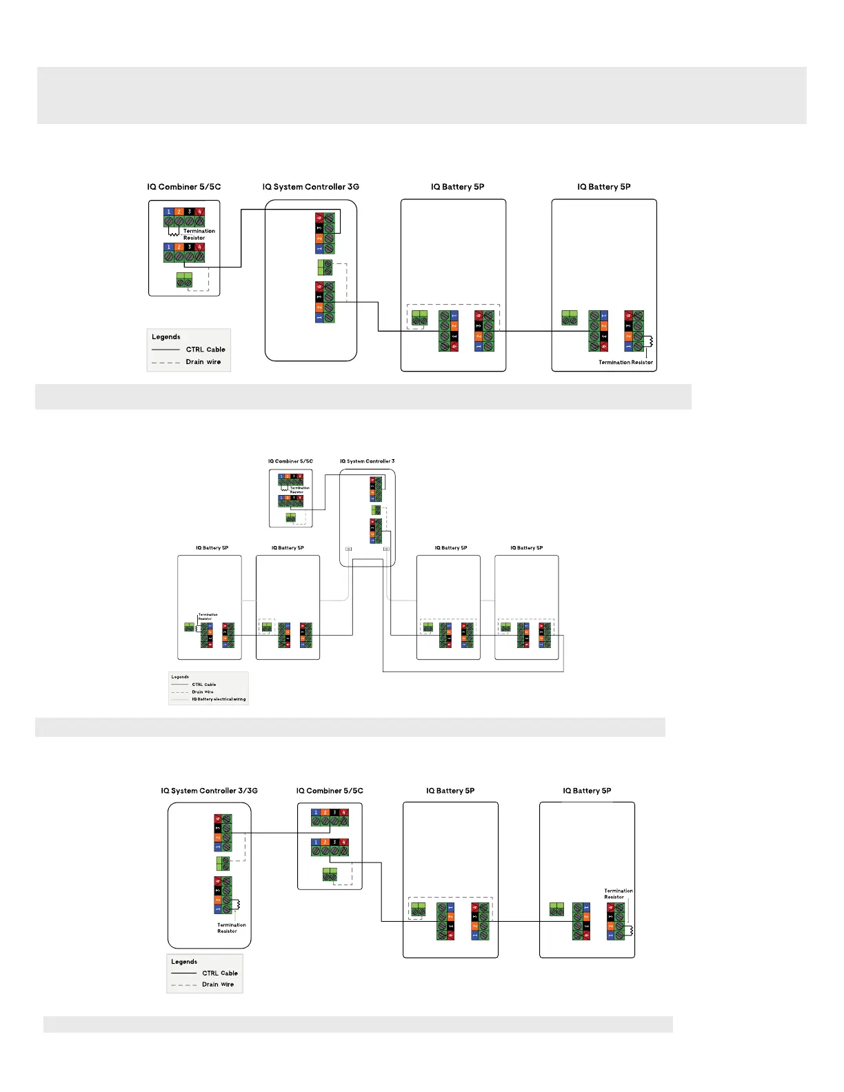
Control (CTRL) wiring between system components
When installing the control wiring for the system, refer to the following wiring sequences to best understand the termination resistor header position, control
wiring order, and drain wire termination location.
NOTE: Ensure following guidelines are followed to ensure no failures during system commissioning:
1. One header with termination resistor should be installed on each component that is at the extreme end of the control network.
2. It is recommended that the drain wire be terminated at the component from which the control wiring for the section is initiated.
3. Same conduits can be used for power and control wire routing only when using Enphase CTRL cable i.e CTRL-SC3-NA-01.
Following are the four common wiring sequences:
Sequence 1b : IQ Combiner 5/5C -> IQ System Controller 3 -> IQ Battery(s) 5P
Sequence 2: IQ System Controller 3/3G -> IQ Combiner 5/5C -> IQ Battery(s) 5P
NOTE: Total length of CTRL wiring across the system should not exceed 250 feet to ensure the system operates as per specications
NOTE: Total length of CTRL wiring across the system should not exceed 250 feet to ensure system operates as per specications
NOTE: Total length of CTRL wiring across the system should not exceed 250 feet to ensure system operates as per specications
Sequence 1a: IQ Combiner 5/5C -> IQ System Controller 3G -> IQ Battery(s) 5P
This is only applicable to IQ System Controller 3 where the third DER port can be used for additional batteries
 Loading...