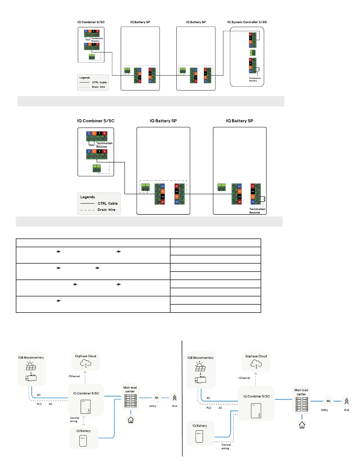
Sequence 3: IQ Combiner 5/5C -> IQ Battery(s) 5P -> IQ System Controller 3/3G
NOTE: Total length of CTRL wiring across the system should not exceed 250 feet to ensure system operates as per specications
Sequence 4*: IQ Combiner 5/5C -> IQ Battery(s) 5P
Table below provides the termination resistor locations for the above sequences:
Control wiring sequence Termination resistor location
IQ Combiner 5/5C IQ System Controller 3/3G IQ Battery(s) 5P IQ Combiner 5/5C
Last IQ Battery 5P in the daisy chain
IQ Combiner 5/5C IQ Battery(s) 5P IQ System Controller 3/3G IQ Combiner 5/5C
IQ System Controller 3/3G
IQ System Controller 3/3G IQ Combiner 5/5C IQ Battery(s) 5P IQ System Controller 3/3G
Last IQ Battery 5P in the daisy chain
IQ Combiner 5/5C IQ Battery(s) 5P IQ Combiner 5/5C
Last IQ Battery 5P in the daisy chain
*Grid-tied system conguration
NOTE: Total length of CTRL wiring across the system should not exceed 250 feet to ensure system operates as per specications
IQ Combiner 5/5C can be used with IQ Battery 5P without an IQ System Controller 3/3G for Grid-tied systems
Home loads
Wi-Fi
power
line
line
and
meter
cellular
over
Home loads
Wi-Fi
line
line
over
power
manager
and
cellular
IQ Battery 5P connected to main load center
IQ Battery 5P connected to IQ Combiner 5/5C
 Loading...