Installing and Connecting a Redundant Power System
Enterasys A4 Fast Ethernet Switch Hardware Installation Guide 2-17
STK-RPS-500PS
The STK-RPS-500PS provides power backup to an Enterasys PoE-compliant A4 stackable switch.
If for some reason the switch looses power from its internal power supply, the STK-RPS-500PS can
provide up to 500 watts maximum operating power to support switch operation and the 48 Vdc
necessary to support 48 Vdc/data connections to PDs (Powered Devices).
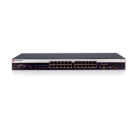
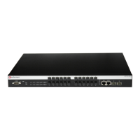
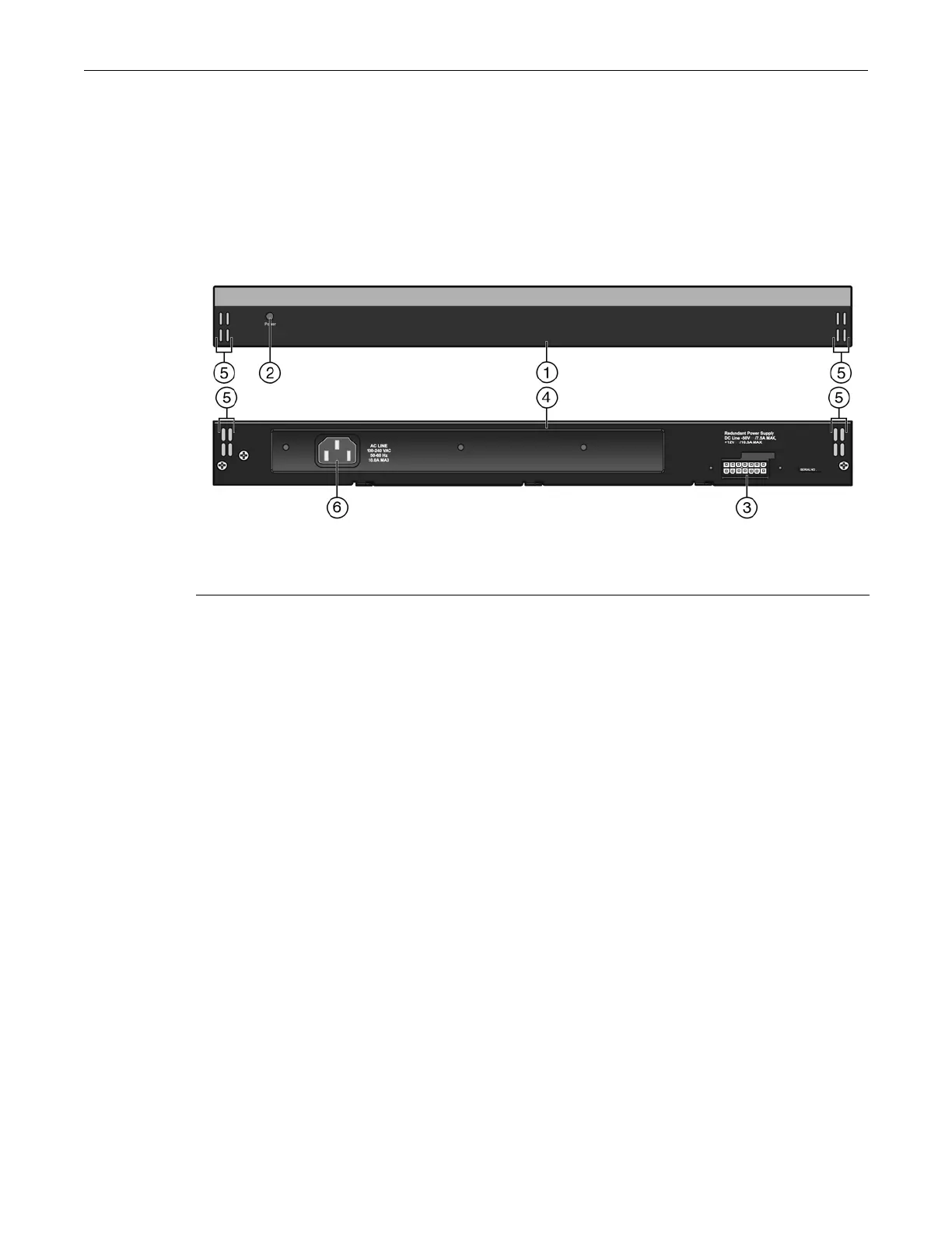
Figure 2-11 shows the front and rear view of the STK-RPS-500PS power supply.
Figure 2-11 STK-RPS-500PS (front and rear view)
The STK-RPS-500PS is shipped with the following:
•AC power cord
• RPS cable (1 meter in length)
• Four rubber feet (for flat surface installation)
•Two rack mount brackets
• Eight flathead screws (M3x6)
Installing the STK-RPS-500PS
You can install the STK-RPS-500PS on a flat surface or in a 19-inch rack.
Locate the STK-RPS-500PS within 152 cm (5 ft) of its power source.
Rack Mounting the STK-RPS-500PS
To install the STK-RPS-500PS in a 19-inch rack, you need:
• Two rackmount brackets and mounting screws (rackmount kit) shipped with the
STK-RPS-500PS.
• Four customer-supplied screws to attach the STK-RPS-500PS to a standard 19-inch rack.
To install an STK-RPS-500PS in the shelf:
1. Attach the rackmount brackets to the STK-RPS-500PS, as shown in Figure 2-12, using the eight
M3 x 6 mm flathead screws shipped with the STK-RPS-500PS.
1 STK-RPS-500PS (front view) 4 STK-RPS-500PS (rear view)
2 LED status indicator 5 Air vents for cooling
3 Redundant Power Supply connector 6 AC power input connector
 Loading...