Amulet High Definition Television Receiver User’s Guide
Copyright © 2008 Entone, Inc. All rights reserved
.
8
FRONT PANEL AND REAR PANEL
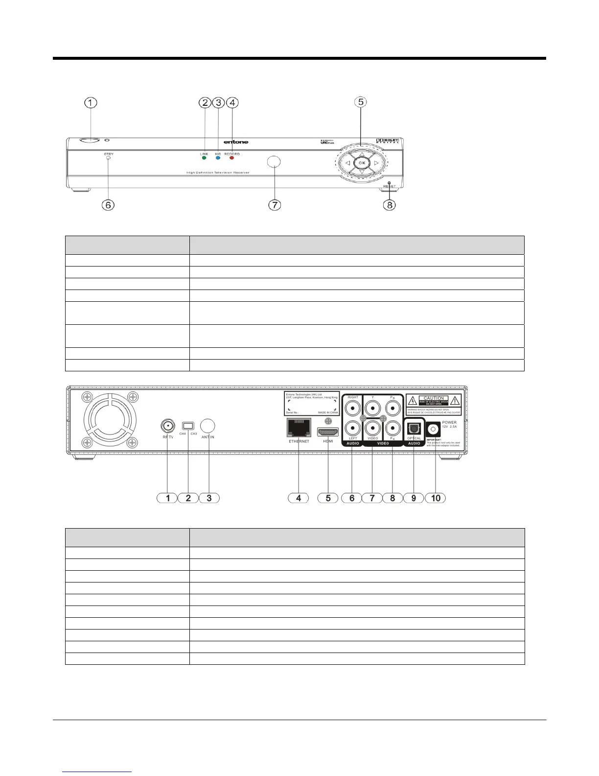
Figure 2-1 Amulet Front Panel
Part Name Description
1. Standby Switch Power up or put Amulet in standby mode
2. LINK Indicator Green when Ethernet connection is active
3. HD Indicator Blue when the output resolution is HD (720p or higher)
4. RECORD Indicator Red when PVR (Personal Video Recording) is recording
5. Arrow Keys and OK
Button
OK Button for triggering remote registration mode
Other usage according to middleware
6. Standby / On Indicator Orange in standby mode and starting
Green when started
7. IR receiver Remote control IR receiver
8. Reset Pin Hole Restart Amulet
Figure 2-2 Amulet Rear Panel
Part Name Description
1. RF TV Type-F connector for RF TV output (factory set to channel 3 or channel 4)
2. CH4/CH3 Switch Switch for toggling the RF TV default channel (either channel 3 or channel 4)
3. ANT IN Type-F connector for ANTENNA IN to connect to cable wall outlet
4. ETHERNET RJ45 plug for connecting to ADSL modem or network access equipment
5. HDMI HDMI output
6. AUDIO LEFT / RIGHT Composite audio output
7. VIDEO Composite video output
8. Y Pb Pr Component video output
9. DIGITAL AUDIO S/PDIF digital audio output
10. DC INPUT DC power jack