EasyManua.ls Logo

Enttec Open DMX Ethernet User Manual

Enttec Open DMX Ethernet
19 pages
To Next Page IconTo Next Page
To Previous Page IconTo Previous Page
Page #7 background image
Introduction
Thank you for buying the ODE. At ENTTEC we are proud of our products and
we hope you will enjoy them as much as we enjoy making them.
Firstly, unpack the unit from the box. You will find:
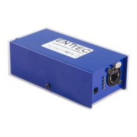
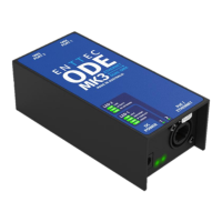
the ODE, which is a box containing all the electronics
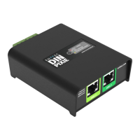
an external power supply (not included on the Power Over Ethernet model)
a CD containing the NMU program,
and this manual.
If you are missing any parts, please contact the dealer through whom you
purchased the unit to arrange a solution.
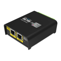
On the front of the ODE device, you will find :
RJ45 Ethercon connector for a 10/100 Base-T Ethernet connection
4 Status LEDS
DC 9V input power jack for connecting the included Power Supply
(not included on the POE Model)
On the back you will find:
1 DMX output connector
1 DMX input connector
The unit has no power switch and can be left on continuously.
Features
1 DMX port with Male and Female connectors
Setup done through Node Management Utility
Supports ESP and Art-Net protocols for DMX over Ethernet
ODE User Manual 7
Question and Answer IconNeed help?

Do you have a question about the Enttec Open DMX Ethernet and is the answer not in the manual?

Enttec Open DMX Ethernet Specifications

General IconGeneral
BrandEnttec
ModelOpen DMX Ethernet
CategoryController
LanguageEnglish

Summary

Contacting ENTTEC

Warranty

Glossary

Introduction

Features

Limitations

Basic Concept

Connector Pin Out

DMX OUT Pin Configuration

Specifies the pin assignments for the DMX output connector including Ground and Data pins.

DMX IN Pin Configuration

Specifies the pin assignments for the DMX input connector including Ground and Data pins.

Getting Started

Default DMX Port and Ethernet Channels

Outlines the default settings for DMX output and Ethernet Universe 0,0.

LED Status Indicators

Explains the meaning of the four status LEDs on the ODE device.

NMU Configuration

Updating the Application Firmware

Emergency Firmware Update

Appendix 1: FCC Declaration

Appendix 2: CE Compliance

Related product manuals