Envent Engineering Ltd. Page 14 Revision 2.4
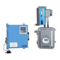
Make sure to leave at least 1 feet of extra space on the left side of the 330S H
2
S
analyzer. This will allow proper opening of the side door located at the upper blue
chassis where the H
2
S sensing tape is located.
Sample Point Selection
The sample to the 330S/331S H
2
S analyzer must be representative of the process
stream and should be taken from a point as close as possible to the analyzer to avoid
lag times and sample degradation in the tubing. A probe must be installed vertically
on a horizontal section of pipe ensuring that the sample is drawn from the middle third
of the pipeline.
An optional Genie GPR Probe regulator may be used. The function of this probe is to
ensure a clean dry sample to the analyzer and to reduce the pressure of the sample.
The lower pressure will improve the response time of the analyzer. Refer to Figure 4.
It is advisable that the probe not be installed on a vertical pipe.
Sample inlet & sample sweep
1/4 inch 316 stainless steel tubing and fittings are recommended for the sample inlet
and sample sweep tubing. Sample sweep can be connected to a flare line if available.
Refer to Figure 4.
1/8 inch 316 stainless steel tubing can also be used if the response time of the
analyzer is of particular concern.
Vent line
3/8 inch stainless steel tubing and fittings are recommended for the vent line to a
maximum of 6 feet in length. 1/2 inch stainless steel tubing should be used for vent
lines exceeding 6 feet. The tubing should be installed with a slight downward slope
and should be as short as possible. Refer to Figure 4.
The sample vent line must be tubed to atmospheric pressure outside and cannot be
connected to a flare line or header.