U Page 11
Digital controller RK 4004
In normal circumstances the display on the controller card indicates
only three dots. These three dots signal that no errors are present .
A flashing number signals an error. The number indicates the error
code. If several errors are present at the same time, the error with the
highest priority will be indicated. If this error is no longer present, the
display will indicate the next error.
Below is a list of possible errors:
4.2.2 Current error display
No. Error display in Description Output at
CANMON terminal X 20.4
1 UDC-power low 19.5 VDC operating voltage not attained 0
2 UDC-power high 30.5 VDC operating voltage exceeded 0
3 I motor high set maximum cut-off current exceeded -
4 temp case high heat sink over 70
o
C0
5 encoder fault incremental encoder motor fault -
6 encoder invers incremental encoder motor inverted -
7 sensor R fault no message from right sensor -
8 sensor L fault no message from left sensor -
9 gearconstant fault calculated gear constant produces impermissible value -
10 motor line fault motor line interrupted 0
12 power stage defect motor power stage defective 0
13 motor blocked motor blocked due to overloading (I = max. & n = 0)
Attention! output is set after 5 seconds only 0
14 ref. switch error several reference switch errors detected. -
15 end switch error end position proximity switches incorrectly configured -
16 24Vext. fault ext. supply voltage overloaded. 0
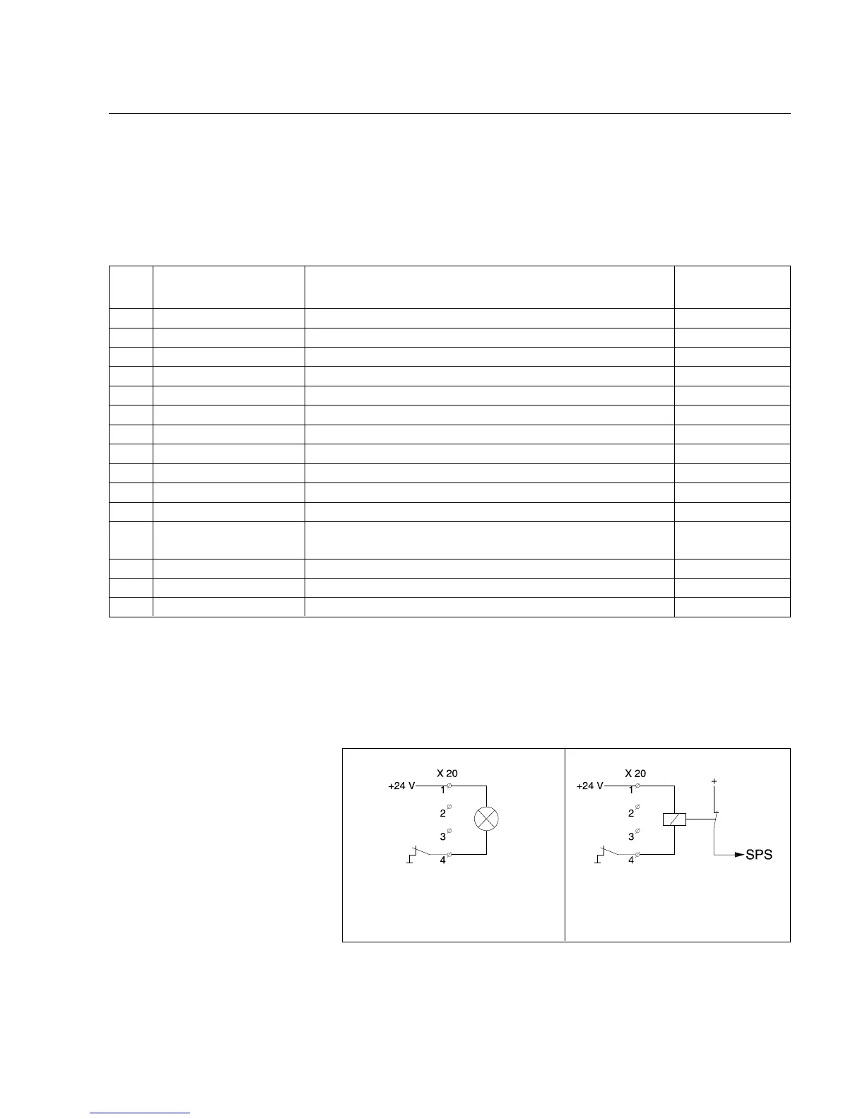
4.2.3 Output X 20.4 In the case of certain errors (see table) output X 20.4 is switched to
"0". The internal switch on the controller card that furnishes a con-
nection to ground is opened.
The following circuit variants are recommended:
Lamp "ON" = system on stand-by
Lamp "OFF" = error
PLC "1" = system on stand-by
PLC "0" = error