L200/L201/L100/L101 Revision A
Disassembly/Assembly Details of Disassembling/Reassembling by Parts/Unit 28
Confidential
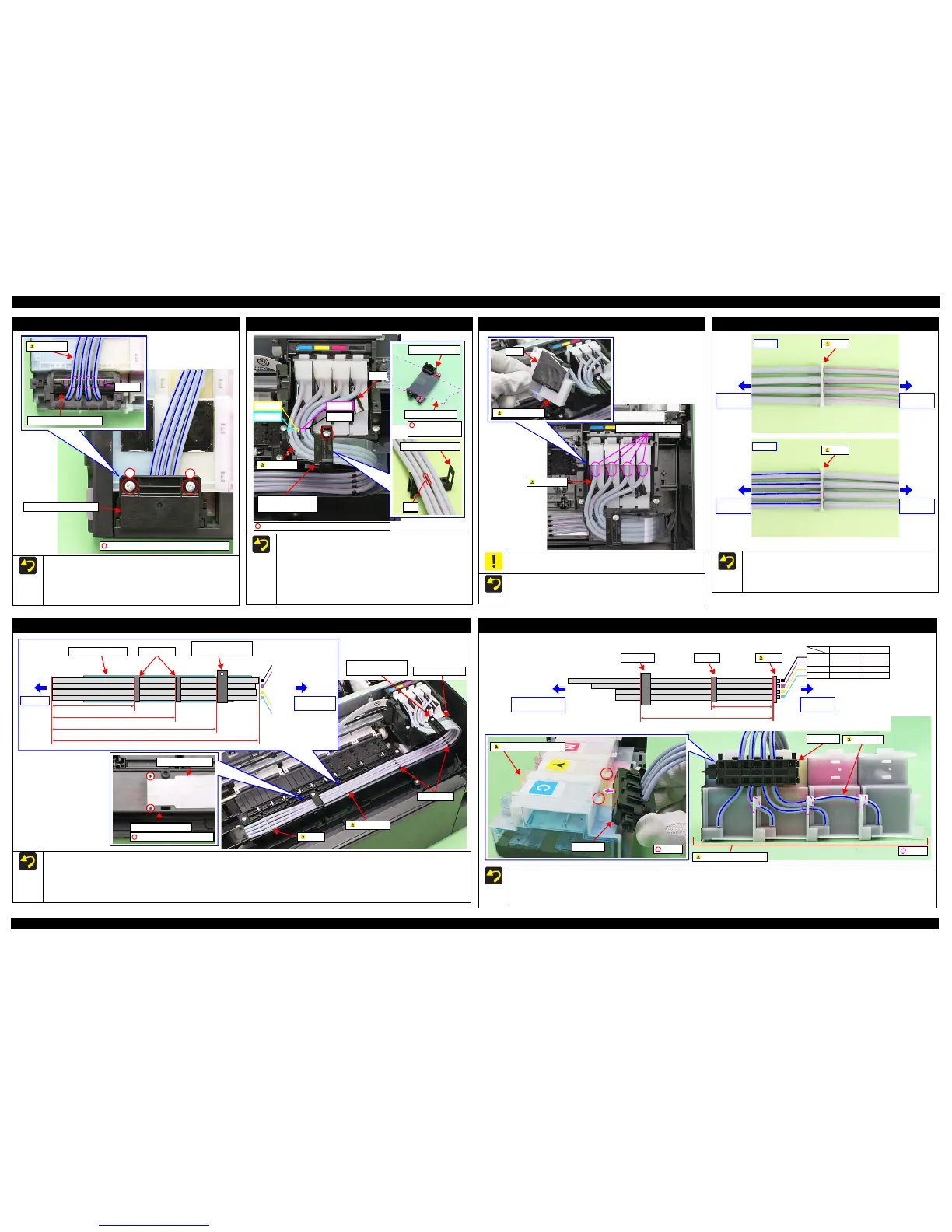
Tube Valve Holder Rear / Tube Valve Holder Front
When installing the Tube Valve Holder Front, align the blue
lines (the red lines for L100/L101) of the ink tubes in the same
direction as shown in the figure above, and route them through
the grooves of the Tube Valve Holder Front.
Tighten the screws in the order indicated in the figure above.
1
C.B.P-TITE SCREW 3x6 (5.0 ~ 6.0 kgf·cm)
2
Tube Valve Holder Front
Grooves
Ink Tubes
Tube Hol der Top / Tube Hol der Low er
Align the positioning holes (x2) of the Tube Guide Plate with
the dowels (x2) of the Tube Holder Top.
Route the ink tubes while avoiding the rib of the Tube Holder
Lower to prevent the tubes from getting caught by the tube holders.
Make sure to route the ink tubes as shown in the figure above
when installing the Tube Holder Top/Tube Holder Lower.
Route the ink tubes over the films of the Adapter Assy.
C.B.P-TITE SCREW 2.6x16 (5.0 ~ 6.0 kgf·cm)
Cyan
Yellow
Black
Magenta
Tube Holder Top/
Tube Holder Lower
Film
Ink Tubes
Tube Holder Top
Tube Guide Plate
Positioning hole
and dowel
Adapter Assy
Be careful not to damage or peel off the film of the Adapter Assy.
When installing the ink tubes to the Adapter Assy, insert the ink
tubes with their red lines facing upward as shown in the figure
above.
Opening for Ink Tubes
Ink Tubes
Joint
Align the red lines and blue lines (the other red lines for L100/
L101) respectively in the same direction as shown in the figure
above, and insert them to the joint to the full to its base.
Be careful not to damage the ink tubes and joint.
Valve Assy
side
Valve Assy
side
Tube Assy
side
Tube Assy
side
Front
Joint
Joint
Back
Tube Assy
Before installing the Tube Assy, align the positioning holes (x2) of the Tube Guide Plate with the dowels (x2) of the Ink Tube Guide 2nd.
When installing the Tube Assy, attach the Clamps (x2)/Tube Holder Top/Tube Holder Lower/Tube Guide Plate in the positions shown in the
figure above.
When installing the Tube Assy, align the red lines of the ink tubes in the same direction as shown in the figure above, and attach them without
any slack.
190 ± 1 mm
257 ± 1 mm
335 ± 1 mm
420 ± 4.2 mm or 10% tolerance
Black
Magenta
Yellow
Cyan
Joint side
Adapter Assy
side
Tube Guide Plate Clamps (x2)
Tube Holder Top/
Tube Holder Lower
Tube Guide Plate
Tube Holder Top/
Tube Holder Lower
Clamps (x2)
Joint
Tube Assy
Ink Tube Guide 2nd
Tube Guide Plate
Positioning hole and dowel
Valv e As sy
When installing the Valve Assy, attach the Clamp on the position shown in the figure above.
When installing the Valve Assy, align the blue lines of the ink tubes (the red lines for L100/L101) in the same direction as shown in the figure
above, and route them through the holes of the Ink Supply Tank Assy.
When installing the Valve Assy, secure it with the hooks (x2) of the Ink Supply Tank Assy.
165 ± 1 mm
L200/L201: 310 mm
L100/L101: 290 mm
380 mm400 mm
L100/L101L200/L201
350 mm370 mm
325 mm345 mm
325 mm345 mm
Black
Magenta
Yellow
Cyan
ClampValve case
Valve case
Tube Assy
side
Ink Supply Tank
Assy side
Hole
Length of Ink Tube
Joint
Ink Supply Tank Assy
Ink Tube
Valve Assy
Ink Supply Tank Assy
Hook