L350/L300/L355/L210/L110 Series Revision B
Disassembly/Reassembly Detailed Disassembly/Reassembly Procedure for each Part/Unit 41
Confidential
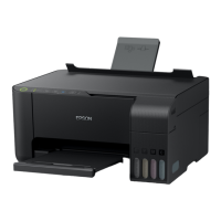
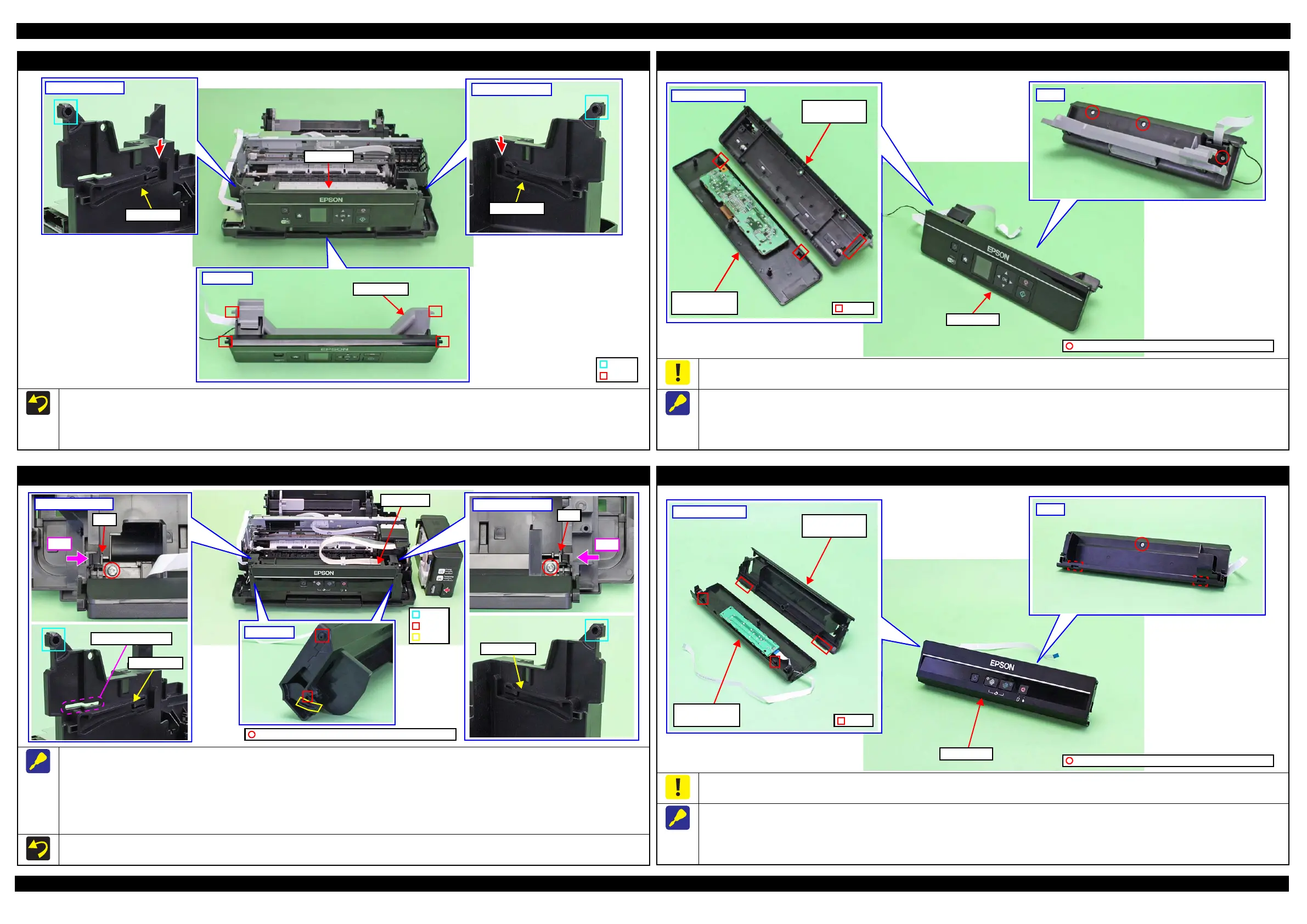
Panel Unit (L355 Series)
When installing the Panel Unit, follow the procedure below.
1. Route the Panel FFC and grounding wire through the holes of the Frame Base. (p 49)
2. Insert the dowels (x2) of the Panel Stand into the grooves on both sides of the Frame Base from the sections indicated in the arrows shown above.
3. Insert the dowels (x2) of the Panel Unit into the holes (x2) of the Frame Base, and secure the Panel Unit to the Frame Base.
Frame Base (left)
Rail section
Frame Base (right)
Rail section
Panel Unit
Panel Stand
Panel Unit
Hole
Dowel
Panel Housing Lower Assy (L355 Series)
Be careful not to damage the hooks (x2) of the Panel Housing Upper Assy when releasing them.
When removing the Panel Housing Lower Assy, follow the procedure below.
1. Remove the screws (x3) on the back of the Panel Unit.
2. Widen the upper side of the Panel Unit slightly to release the hook of the Panel Housing Lower Assy.
3. Release the hooks (x2) of the Panel Housing Upper Assy one by one, and remove the Panel Housing Lower Assy.
Hook
Inside Panel Unit
Panel Housing
Upper Assy
Panel Housing
Lower Assy
C.B.P-TITE SCREW 3x10 F/ZN-3C (6 ± 1 kgf·cm)
Back
Panel Unit
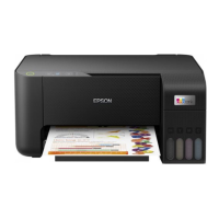
Panel Unit (L350/L210 Series)
When removing the Panel Unit, follow the procedure below.
1. Remove the two screws that secure the Panel Unit.
2. Pull out the shaft on the both ends of the Panel Unit from the holes of the Frame Base.
3. While pressing the right and left tabs on the rear of the Panel Unit inward, disengage the two dowels and two ribs of the Panel Unit from the rail
of the Frame Base.
4. Pull out the Panel FFC through the hole of the Frame Base, and remove the Panel Unit.
Tighten the screws in the order indicated in the figure above.
Frame Base (left)
Push
Tab
Frame Base (right)
Push
Tab
Panel Unit
Hole
Shaft
Rail section
Rail section
Hole of Frame Base
Panel Unit
C.B.P-TITE SCREW 3x10 F/ZN-3C (6 ± 1 kgf·cm)
Rib
Panel Housing Lower Assy (L350/L210 Series)
Be careful not to damage the hooks (x2) of the Panel Housing Lower Assy when releasing them.
When removing the Panel Housing Lower Assy, follow the procedure below.
1. Remove the screws (x1) on the back of the Panel Unit.
2. Disengage the two hooks of the Panel Housing Upper Assy one by one.
3. Disengage the two hooks of the Panel Housing Lower Assy, and remove the assy.
Hook
Inside Panel Unit
Panel Housing
Upper Assy
Panel Housing
Lower Assy
C.B.P-TITE SCREW 3x10 F/ZN-3C (6 ± 1 kgf·cm)
Back
Panel Unit
 Loading...